TERMINALS OF ECU
System information
| MULTIPLEX NETWORK MASTER SWITCH (DRIVER) |


Disconnect the M7 (L17) switch connector.
Measure the voltage and resistance of each terminal according to the value(s) in the table below.
- Resistance:
Symbols (Terminal No.)
Wiring Color
Terminal Description
Condition
Specified Condition
GND (2) - Body ground
W-B - Body ground
Ground
Always
Below 1 Ω
- Voltage:
Symbols (Terminal No.)
Wiring Color
Terminal Description
Always
Specified Condition
BDR (10) - GND (2)
L - W-B
+B power supply
Always
10 to 14 V
CPUB (9) - GND (2)
G - W-B
+B power supply
Always
10 to 14 V
SIG (20) - GND (2)
B - W-B
Ignition power supply
Engine switch OFF → ON (IG)
0 V → 10 to 14 V
Reconnect the M7 (L17) switch connector and reset the power window motor.
Measure the voltage according to the value(s) in the table below.
- Voltage:
Symbols (Terminal No.)
Wiring Color
Terminal Description
Condition
Specified Condition
UP (1) - GND (2)
R - W-B
Power window motor UP output
Engine switch on (IG), driver side power window switch OFF → UP (Manual operation)
0 V → 10 to 14 V
UP (1) - GND (2)
R - W-B
Power window motor UP output
Engine switch on (IG), driver side power window fully open → driver side power window switch UP (AUTO operation) → driver side power window fully closed
0 V → 10 to 14 V → 0 V
DN (11) - GND (2)
G - W-B
Power window motor DOWN output
Engine switch on (IG), driver side power window switch OFF → DOWN (Manual operation)
10 to 14 V → 0 V
DN (11) - GND (2)
G - W-B
Power window motor DOWN output
Engine switch on (IG), driver side power window fully closed → driver side power window switch DOWN (AUTO operation) → driver side power window fully open
10 to 14 V → 0 V
PWS (6) - GND (2)
P - W-B
Power window lock switch output
Engine switch on (IG), power window lock switch UNLOCK → LOCK
10 to 14 V → 0 V
VCC (19) - GND (2)
LG - W-B
Power window motor power source
Engine switch on (IG), driver side power window switch OFF → UP or OFF → DOWN
0 V → 10 to 14 V
| CHECK MULTIPLEX NETWORK SWITCH (FRONT PASSENGER SIDE) |

Disconnect the M16 (L13) switch connector.
Measure the voltage and resistance according to the value(s) in the table below.
- Resistance:
Symbols (Terminal No.)
Wiring Color
Terminal Description
Condition
Specified Condition
GND (7) - Body ground
W-B - Body ground
Ground
Always
Below 1 Ω
- Voltage:
Symbols (Terminal No.)
Wiring Color
Terminal Description
Condition
Specified Condition
BDR (12) - GND (7)
L - W-B
+B power supply
Always
10 to 14 V
Reconnect the M16 (L13) switch connector and reset the power window motor.
Measure the voltage according to the value(s) in the table below.
- Voltage:
Symbols (Terminal No.)
Wiring Color
Terminal Description
Condition
Specified Condition
UP (6) - GND (7)
R - W-B
Power window motor UP output
Engine switch on (IG), front passenger side power window switch OFF → UP (Manual operation)
0 V → 10 to 14 V
UP (6) - GND (7)
R - W-B
Power window motor UP output
Engine switch on (IG), front passenger side power window fully open → front passenger side power switch UP (AUTO operation) → front passenger side power window fully closed
0 V → 10 to 14 V → 0 V
DN (1) - GND (7)
G - W-B
Power window motor DOWN output
Engine switch on (IG), front passenger side power window switch OFF → DOWN (Manual operation)
10 to 14 V → 0 V
DN (1) - GND (7)
G - W-B
Power window motor DOWN output
Engine switch on (IG), front passenger side power window fully closed → front passenger side power window switch DOWN (AUTO operation) → front passenger side power window fully open
10 to 14 V → 0 V
PCT (11) - GND (7)
P - W-B
Power window lock switch output
Engine switch on (IG), power window lock switch UNLOCK → LOCK
10 to 14 V → 0 V
VCC (5) - SGND (8)
W - L
Power window motor power source
Engine switch on (IG), front passenger side power window switch OFF → UP or OFF → DOWN
0 V → 10 to 14 V
| CHECK MULTIPLEX NETWORK SWITCH (REAR LH) |

Disconnect the O1 switch connector.
Measure the voltage and resistance according to the value(s) in the table below.
- Resistance:
Symbols (Terminal No.)
Wiring Color
Terminal Description
Condition
Specified Condition
GND (O1-7) - Body ground
W-B - Body ground
Ground
Always
Below 1 Ω
SEL2 (O1-10) - GND (O1-7)
W-B - W-B
Terminal for identification of rear LH switch
Always
Below 1 Ω
- Voltage:
Symbols (Terminal No.)
Wiring Color
Terminal Description
Condition
Specified Condition
BDR (O1-12) - GND (O1-7)
O - W-B
+B power supply
Always
10 to 14 V
Reconnect the O1 switch connector and reset the power window motor.
Measure the voltage according to the value(s) in the table below.
- Voltage:
Symbols (Terminal No.)
Wiring Color
Terminal Description
Condition
Specified Condition
UP (O1-6) - GND (O1-7)
R - W-B
Power window motor UP output
Engine switch on (IG), rear LH power window switch OFF → UP (Manual operation)
0 V → 10 to 14 V
UP (O1-6) - GND (O1-7)
R - W-B
Power window motor UP output
Engine switch on (IG), rear LH power window fully open → rear LH power window switch UP (AUTO operation) → rear LH power window fully closed
0 V → 10 to 14 V → 0 V
DN (O1-1) - GND (O1-7)
G - W-B
Power window motor DOWN output
Engine switch on (IG), rear LH power window switch OFF → DOWN (Manual operation)
10 to 14 V → 0 V
DN (O1-1) - GND (O1-7)
G - W-B
Power window motor DOWN output
Engine switch on (IG), rear LH power window fully closed → rear LH power window switch DOWN (AUTO operation) → rear LH power window fully open
10 to 14 V → 0 V
PCT1 (O1-11) - GND (O1-7)
V - W-B
Power window lock switch output
Engine switch on (IG), Power window lock switch UNLOCK → LOCK
10 to 14 V → 0 V
VCC (O1-5) - SGND (O1-8)
W - LG
Power window motor power source
Engine switch on (IG), rear LH side power window switch OFF → UP or OFF → DOWN
0 V → 10 to 14 V
| CHECK MULTIPLEX NETWORK SWITCH (REAR RH) |

Disconnect the N1 switch connector.
Measure the voltage and resistance according to the value(s) in the table below.
- Resistance:
Symbols (Terminal No.)
Wiring Color
Terminal Description
Condition
Specified Condition
GND (N1-7) - Body ground
W-B - Body ground
Ground
Always
Below 1 Ω
SEL1 (N1-9) - GND (N1-7)
W-B - W-B
Terminal for identification of rear RH switch
Always
Below 1 Ω
- Voltage:
Symbols (Terminal No.)
Wiring Color
Terminal Description
Condition
Specified Condition
BDR (N1-12) - GND (N1-7)
O - W-B
+B power supply
Always
10 to 14 V
Reconnect the N1 switch connector and reset the power window motor.
Measure the voltage according to the value(s) in the table below.
- Voltage:
Symbols (Terminal No.)
Wiring Color
Terminal Description
Condition
Specified Condition
UP (N1-6) - GND (N1-7)
R - W-B
Power window motor UP output
Engine switch on (IG), rear RH power window switch OFF → UP (Manual operation)
0 V → 10 to 14 V
UP (N1-6) - GND (N1-7)
R - W-B
Power window motor UP output
Engine switch on (IG), rear RH power window fully open → rear RH power window switch UP (AUTO operation) → rear RH power window fully closed
0 V → 10 to 14 V → 0 V
DN (N1-1) - GND (N1-7)
G - W-B
Power window motor DOWN output
Engine switch on (IG), rear RH power window switch OFF → DOWN (Manual operation)
10 to 14 V → 0 V
DN (N1-1) - GND (N1-7)
G - W-B
Power window motor DOWN output
Engine switch on (IG), rear RH power window fully closed → rear RH power window switch DOWN (AUTO operation) → rear RH power window fully open
10 to 14 V → 0 V
PCT1 (N1-11) - GND (N1-7)
P - W-B
Power window lock switch output
Engine switch on (IG), Power window lock switch UNLOCK → LOCK
10 to 14 V → 0 V
VCC (N1-5) - SGND (N1-8)
W - LG
Power window motor power source
Engine switch on (IG), rear RH side power window switch OFF → UP or OFF → DOWN
0 V → 10 to 14 V
| CHECK MAIN BODY ECU RH (COWL SIDE J/B RH) |
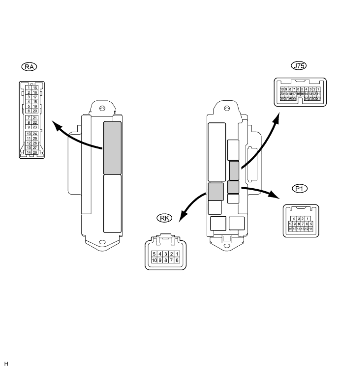
Disconnect the RK connector.
Measure the voltage according to the value(s) in the table below.
- Voltage:
Symbols (Terminal No.)
Wiring Color
Terminal Description
Condition
Specified Condition
BECU (RK-5) - Body ground
G-R - Body ground
Power Supply
Always
10 to 14 V
Reconnect the RK connector.
Measure the resistance according to the value(s) in the table below.
- Resistance:
Symbols (Terminal No.)
Wiring Color
Terminal Description
Condition
Specified Condition
DCTY (P1-14) - Body ground
W - Body ground
Driver side courtesy switch input
Driver side door CLOSED → OPEN
10 kΩ or higher → Below 1 Ω
PCTY (J75-23) - Body ground
B - W-B
Front passenger side courtesy switch input
Passenger side door CLOSED → OPEN
10 kΩ or higher → Below 1 Ω
RCTY (P1-16) - Body ground
O - W-B
Rear RH side courtesy switch input
Rear RH side door CLOSED → OPEN
10 kΩ or higher → Below 1 Ω
LCTY (P1-16) - Body ground
O - W-B
Rear LH side courtesy switch input
Rear LH side door CLOSED → OPEN
10 kΩ or higher → Below 1 Ω