TERMINALS OF ECU
System information
| TELEVISION CAMERA ASSEMBLY |
Disconnect the Q43 camera connector.


Measure the voltage and resistance between each terminal of the wire harness side connector.
If the result is not as specified, there may be a malfunction on the wire harness side.Symbols (Terminal No.)
Wiring Color
Terminal Description
Condition
Specified value
CGND (Q43-3) - Body ground
W - Body ground
Ground
Always
Below 1 Ω
CB+ (Q43-4) - CGND (Q43-3)
B - W
Power source
Engine SW on (IG), shift lever R position
Approx. 6 V
Reconnect the Q43 camera connector.
Measure the voltage and waveform between each terminal of the connector.
If the result is not as specified, the camera may have a malfunction.Symbols (Terminal No.)
Wiring Color
Terminal Description
Condition
Specified value
CV+ (Q43-2) - CV- (Q43-1)
R - Shielded
Display signal
Engine SW on (IG), shift lever R position
See waveform 1
Reference: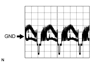
Oscilloscope waveformWaveform 1
Item
Content
Measurement terminal
CV+ - CV-
Measurement setting
0.2 V/DIV., 0.2 μsec./DIV.
Condition
Engine switch on (IG), shift lever reverse position
| TELEVISION CAMERA ECU |
Disconnect the J92 and J93 connectors.
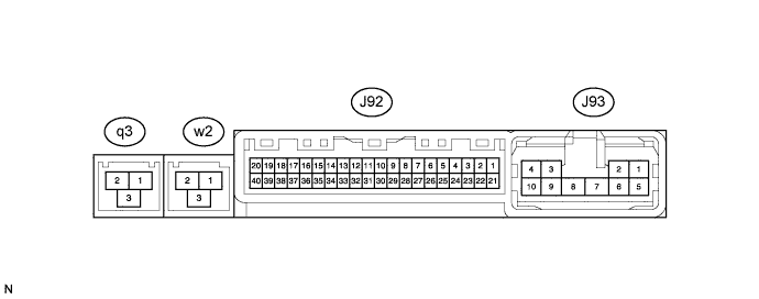
Measure the voltage and resistance between each terminal of the wire harness side connector.
If the result is not as specified, there may be a malfunction on the wire harness side.Symbols (Terminal No.)
Wiring Color
Terminal Description
Condition
Specified value
REV (J92-3) - GND1 (J93-8)
Y - W-B
Reverse signal
Engine switch on (IG), shift position is except reverse
Below 1 V
REV (J92-3) - GND1 (J93-8)
Y - W-B
Reverse signal
Engine switch on (IG), shift position is reverse
10 to 14 V
CANL (J92-6) - Body ground
W - Body ground
CAN control bus
Always
10 kΩ or higher
CANH (J92-7) - Body ground
L - Body ground
CAN control bus
Always
10 kΩ or higher
+B (J93-1) - GND1 (J93-8)
R - W-B
Power source
Always
10 to 14 V
IG (J93-3) - GND1 (J93-8)
B - W-B
IG signal input
Engine switch on (IG)
10 to 14 V
ACC (J93-4) - GND1 (J93-8)
O - W-B
Accessory (ON)
Engine switch off
Below 1 V
ACC (J93-4) - GND1 (J93-8)
O - W-B
Accessory (ON)
Engine switch on (ACC)
10 to 14 V
GND1 (J93-8) - Body ground
W-B - Body ground
Ground
Always
Below 1 V
Reconnect the J92 and J93 connectors.
Measure the voltage and waveform between each terminal of the connector.
Symbols (Terminal No.)
Wiring Color
Terminal Description
Condition
Specified value
CV- (J92-19) - GND1 (J93-8)
Shielded - W-B
Television camera ground (Shielded)
Always
Below 1 V
CV+ (J92-20) - GND1 (J93-8)
R - W-B
Television camera display signal input
Engine switch on (IG), shift lever in reverse
Pulse generation
Refer to waveform 1
TX- (J92-28) - GND1 (J93-8)
R - W-B
AVC-LAN communication signal
Engine switch on (ACC)
2 to 3 V
TX+ (J92-29) - GND1 (J93-8)
BR - W-B
AVC-LAN communication signal
Engine switch on (ACC)
2 to 3 V
CGND (J92-39) - GND1 (J93-8)
W - W-B
Television camera ground
Always
Below 1 V
CB+ (J92-40) - GND1 (J93-8)
B - W-B
Power source to television camera
Engine switch on (IG), shift lever in reverse position
Approx. 6 V
GVI+ (q3-1) - GND1 (J93-8)
-
Digital image signal (Input)
Navigation display is on
Pulse generation
GVI- (q3-2) - GND1 (J93-8)
-
Digital image signal (Input)
Navigation display is on
Pulse generation
GVG1 (q3-3) - Body ground
-
Ground
Always
Below 1 V
GVO+ (w2-1) - GND1 (J93-8)
-
Digital image signal (Output)
Navigation or television camera display is on
Pulse generation
GVO- (w2-2) - GND1 (J93-8)
-
Digital image signal (Output)
Navigation or television camera display is on
Pulse generation
GVG1 (w2-3) - Body ground
-
Ground
Always
Below 1 V
Reference:
Oscilloscope waveformWaveform 1
Item
Content
Measurement terminal
CV+ - GND1
Measurement setting
0.2 V/DIV., 0.2 μsec./DIV.
Condition
Engine switch on (IG), Shift lever reverse position
| MULTI-DISPLAY (Click here) |