Front Passenger Side Seat Belt Warning Light Malfunction
Circuit diagnosis
DESCRIPTION
with Navigation System:The combination meter assembly detects the state of the front seat inner belt assembly RH when the front passenger seat is occupied with the engine switch on (IG). If the front passenger seat belt is not fastened, the front seat belt warning light on the multi-media module display blinks. If the seat belt is fastened, the warning light goes off.
without Navigation System:
The combination meter assembly detects the state of the front seat inner belt assembly RH when the front passenger seat is occupied with the engine switch on (IG). If the front passenger seat belt is not fastened, the front seat belt warning light on the integration control & panel assembly blinks. If the seat belt is fastened, the warning light goes off.
WIRING DIAGRAM
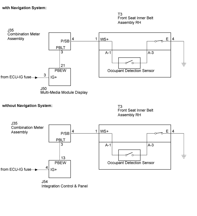

INSPECTION PROCEDURE
| 1. PERFORM ACTIVE TEST BY INTELLIGENT TESTER |

Operate the intelligent tester according to the steps on the display and select "ACTIVE TEST".
- METER:
Item
Test Details
Diagnostic Note
Indicat. lamp P-seat Belt
P-SEAT BELT indicator light (OFF/ON)
Confirm that the vehicle is stopped with the engine idling
- Result:
OK (without Navigation System)
A
OK (with Navigation System)
B
NG
C
- OK:
- Switch condition (ON/OFF) can be switched by "ACTIVE TEST".
|
|
||||
|
|
||||


| A | |
 |
| 2. CHECK WIRE HARNESS (INTEGRATION CONTROL & PANEL +B) |
Disconnect the integration control & panel connector.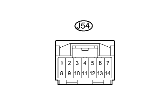
Measure the voltage according to the value(s) in the table below.
- Voltage:
Tester Connection
Condition
Specified Condition
J54-4 (IG+) - Body ground
Engine switch on (IG)
10 to 14 V
|
|
||||
| OK | |
|
| 3. CHECK INTEGRATION CONTROL & PANEL |
Disconnect the integration control & panel connector.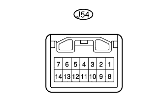
Apply battery voltage to the connector according to the table below.
- Voltage:
Condition
Specified Condition
Battery positive (+) → Terminal 4 (IG)
Battery negative (-) → Terminal 13 (PBEW)
Lights up (Seat belt warning light)
|
|
||||
| OK | |
|
| 4. CHECK WIRE HARNESS (INTEGRATION CONTROL & PANEL - COMBINATION METER ASSEMBLY) |
Disconnect the combination meter assembly and integration control & panel connectors.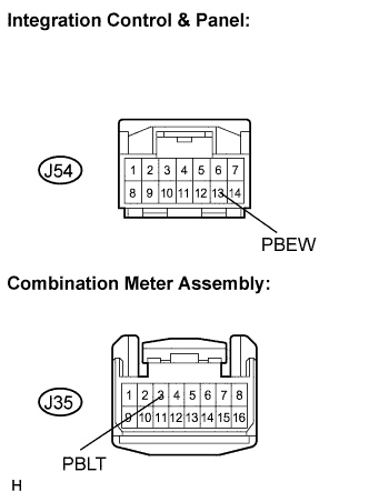
Measure the resistance according to the value(s) in the table below.
- Resistance:
Tester Connection
Condition
Specified Condition
J35-3 (PBLT) - J54-13 (PBEW)
Always
Below 1 Ω
J35-3 (PBLT) - Body ground
Always
10 kΩ or higher
|
|
||||
| NG | ||
 |
||
| ||
| 5. CHECK WIRE HARNESS (MULTI-MEDIA MODULE DISPLAY +B) |
Disconnect the multi-media module display connector.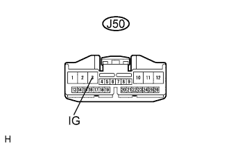
Measure the voltage according to the value(s) in the table below.
- Voltage:
Tester Connection
Condition
Specified Condition
J50-3 (IG+) - Body ground
Engine switch on (IG)
10 to 14 V
|
|
||||
| OK | |
|
| 6. CHECK MULTI-MEDIA MODULE DISPLAY |
Disconnect the multi-media module display connector.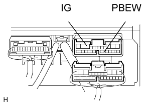
Apply battery voltage to the connector according to the table below.
- Voltage:
Condition
Specified Condition
Battery positive (+) → Terminal 3 (IG)
Battery negative (-) → Terminal 21(PBEW)
Lights up (Seat belt warning light)
|
|
||||
| OK | |
|
| 7. CHECK WIRE HARNESS (MULTI-MEDIA MODULE DISPLAY - COMBINATION METER ASSEMBLY) |
Disconnect the combination meter assembly and multi-media module display connectors.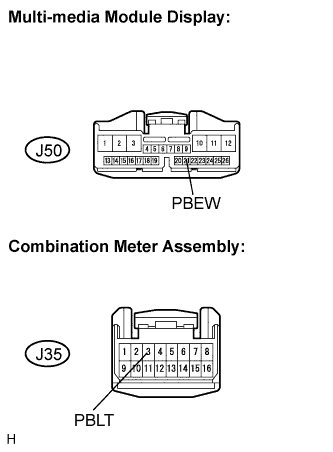
Measure the resistance according to the value(s) in the table below.
- Resistance:
Tester Connection
Condition
Specified Condition
J35-3 (PBLT) - J50-21 (PBEW)
Always
Below 1 Ω
J35-3 (PBLT) - Body ground
Always
10 kΩ or higher
|
|
||||
| OK | |
|
| 8. INSPECT SEPARATE TYPE FRONT SEAT CUSHION COVER (OCCUPANT DETECTION SENSOR) |
Disconnect the occupant detection sensor connector.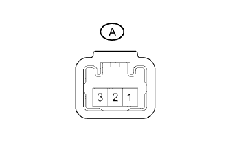
Measure the resistance according to the value(s) in the table below.
- Resistance:
Tester Connection
Condition
Specified Condition
A-1 - A-3
The passenger seat is occupied
Below 100 Ω
A-1 - A-3
The passenger seat is not occupied
Below 1 MΩ
|
|
||||
| OK | |
|
| 9. CHECK WIRE HARNESS (COMBINATION METER ASSEMBLY - FRONT SEAT INNER BELT RH) |
Disconnect the front seat inner belt RH connector.
Measure the resistance according to the value(s) in the table below.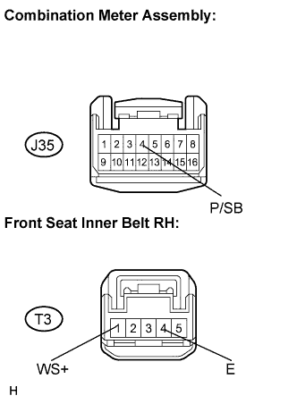
- Resistance:
Tester Connection
Condition
Specified Condition
J35-4 (P/SB) - T3-1 (WS+)
Always
Below 1 Ω
J35-4 (E) - Body ground
Always
10 kΩ or higher
|
|
||||
| OK | |
|
| 10. REPLACE FRONT SEAT INNER BELT ASSEMBLY (PASSENGER SIDE) |
Replace the front seat inner belt assembly (Passenger side).
- OK:
- Seat belt warning operation returns to normal.
|
|
||||
| OK | ||
|
||
| ||