Display Signal Circuit between Navigation ECU and Television Camera ECU
Circuit diagnosis
DESCRIPTION
This is the display signal circuit from the navigation ECU to the television camera ECU.WIRING DIAGRAM
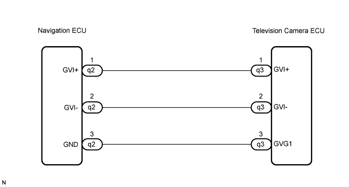

INSPECTION PROCEDURE
| 1. CHECK HARNESS AND CONNECTOR (NAVIGATION ECU - TELEVISION CAMERA ECU) |

Disconnect the navigation ECU connector q2 and television camera ECU connector q3.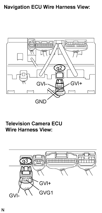
Measure the resistance according to the value(s) in the table below.
- Standard resistance:
Tester connection
Condition
Specified condition
GVI+ - GVI+
Always
Below 1 Ω
GVI- - GVI-
Always
Below 1 Ω
GND - GVG1
Always
Below 1 Ω
GVIF- - Body ground
Always
10 kΩ or higher
GVIF+ - Body ground
Always
10 kΩ or higher
|
|
||||

| OK | ||
 |
||
| ||