C1380/64
Diagnostic trouble codes
DESCRIPTION
Upon receiving the hill-start assist control (HAC) operating signal from the skid control ECU, the relay contact turns on and the stop light comes on.| DTC No. |
DTC Detection Condition |
Trouble Area |
| C1380/64 |
When either of the following is detected:
|
|
WIRING DIAGRAM
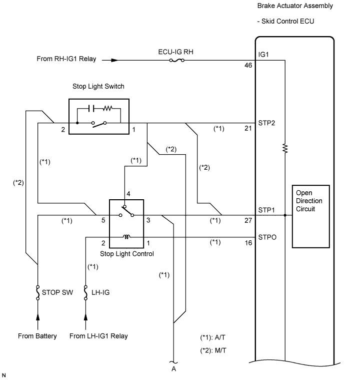

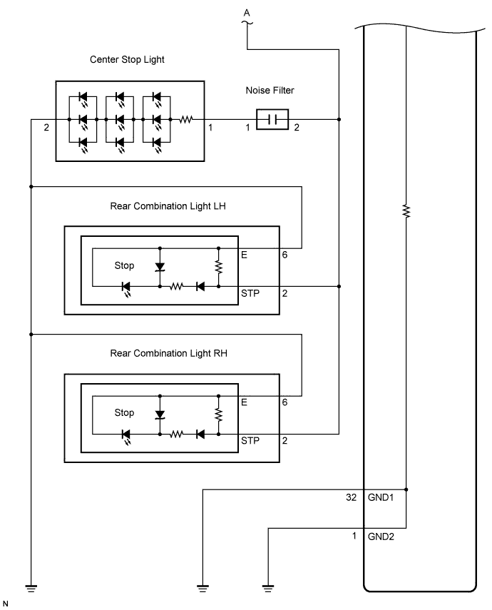
INSPECTION PROCEDURE
- NOTICE:
- When replacing the brake actuator assembly, perform zero point calibration (Click here).
- HINT:
- When C1249/49 is output together with C1380/64, inspect and repair the trouble areas indicated by C1249/49 first.
| 1. INSPECT STOP SW FUSE |

Remove the STOP SW fuse from the main body ECU RH.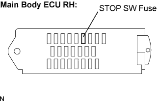
Measure the resistance according to the value(s) in the table below.
- Standard resistance:
Tester Connection
Condition
Specified Condition
STOP SW (7.5 A) fuse
Always
Below 1 Ω
|
|
||||

| OK | |
 |
| 2. CHECK STOP LIGHT OPERATION |
Install the STOP SW fuse.
Check that the stop light comes on when the brake pedal is depressed, and goes off when the brake pedal is released.
- OK:
Condition
Illumination Condition
Brake pedal depressed
ON
Brake pedal released
OFF
|
|
||||
| OK | |
|
| 3. INSPECT SKID CONTROL ECU (STP1 TERMINAL) |
Disconnect the skid control ECU connector.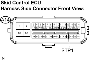
Measure the voltage according to the value(s) in the table below.
- Standard voltage:
Tester Connection
Condition
Specified Condition
A14-27 (STP1) - Body ground
Stop light switch ON (Brake pedal depressed)
8 to 14 V
A14-27 (STP1) - Body ground
Stop light switch OFF (Brake pedal released)
Below 1.5 V
|
|
||||
| OK | |
|
| 4. INSPECT SKID CONTROL ECU (STP2 TERMINAL) |
Measure the resistance according to the value(s) in the table below.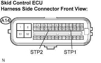
- Standard resistance:
Tester Connection
Condition
Specified Condition
A14-27 (STP1) - A14-21 (STP2)
Always
Below 1 Ω
|
|
||||
| OK | |
|
| 5. PERFORM ACTIVE TEST BY INTELLIGENT TESTER (STOP LIGHT CONTROL RELAY) |
Reconnect the skid control ECU connector.
Connect the intelligent tester to the DLC3.
Start the engine.
Select the Active Test mode on the intelligent tester.
ABS / VSC: Item (Display)
Measurement Item / Range (Display)
Normal Condition
Stop Lamp Relay
Turns stop light control relay ON / OFF
Stop light comes on (Does not come on for 5 seconds or more)
Check that the "ON" and "OFF" of the stop light can be shown on the rear combination light by the intelligent tester.
- OK:
- The stop light turns on or off in accordance with the intelligent tester.
|
|
||||

| NG | |
|
| 6. INSPECT STOP LIGHT CONTROL RELAY |
Turn the engine switch off.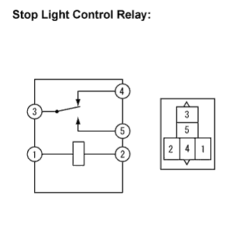
Remove the stop light control relay.
Measure the resistance according to the value(s) in the table below.
- Standard resistance:
Tester Connection
Condition
Specified Condition
3 - 4
Always
Below 1 Ω
3 - 5
Always
10 kΩ or higher
3 - 4
When battery positive voltage is applied to terminal 1 and battery negative voltage to terminal 2
10 kΩ or higher
3 - 5
When battery positive voltage is applied to terminal 1 and battery negative voltage to terminal 2
Below 1 Ω
|
|
||||
| OK | |
|
| 7. INSPECT STOP LIGHT CONTROL RELAY (POWER SOURCE TERMINAL) |
Measure the voltage according to the value(s) in the table below.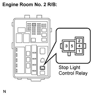
- Standard voltage:
Tester Connection
Condition
Specified Condition
Stop light control relay terminal 5 - Body ground
Always
8 to 14 V
Stop light control relay terminal 2 - Body ground
Engine switch on (IG)
8 to 14 V
|
|
||||
| OK | |
|
| 8. INSPECT SKID CONTROL ECU (STPO TERMINAL) |
Turn the engine switch off.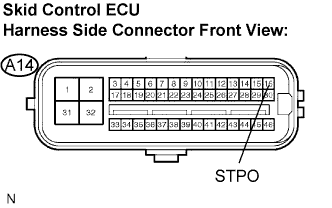
Install the stop light control relay.
Disconnect the skid control ECU connector.
Turn the engine switch on (IG).
Measure the voltage according to the value(s) in the table below.
- Standard voltage:
Tester Connection
Condition
Specified Condition
A14-16 (STPO) - Body ground
Engine switch on (IG)
10 to 14 V
|
|
||||
| OK | |
|
| 9. RECONFIRM DTC |
Turn the engine switch off.
Reconnect the skid control ECU connector.
Clear the DTC (Click here).
Check if the same DTC is recorded (Click here).
- Result:
Condition
Proceed to
DTC (C1380/64) is not output
A
DTC (C1380/64) is output
B
|
|
||||
| A | ||
 |
||
| ||