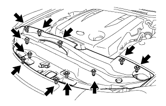
INSTALLATION
Removal / installation
| 1. INSTALL BLOWER ASSEMBLY |

Install the blower assembly with the 2 claws and screw.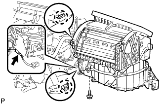

- Torque:
- 3.0 N*m{ 31 kgf*cm , 27 in.*lbf }
Connect the connector.
| 2. INSTALL AIR CONDITIONING AMPLIFIER ASSEMBLY |
Install the air conditioning amplifier with the screw and connect the connector.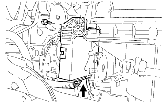
| 3. INSTALL NO. 2 AIR DUCT |
Install the No. 2 air duct with the screw.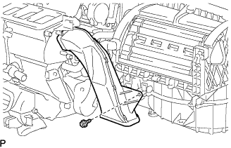
- Torque:
- 5.4 N*m{ 55 kgf*cm , 48 in.*lbf }
| 4. INSTALL AIR CONDITIONER UNIT ASSEMBLY |
Install the air conditioner unit assembly with the 3 bolts and 2 screws.
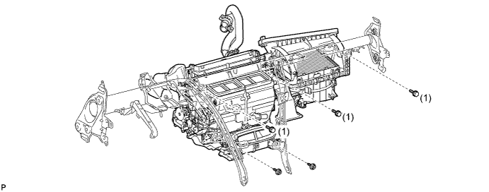
- Torque:
- 9.8 N*m{ 100 kgf*cm , 7 ft.*lbf } (bolt 1)
| 5. INSTALL INSTRUMENT PANEL REINFORCEMENT ASSEMBLY |
Driver seat side:
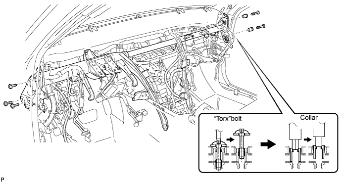
Using a T40 "torx" socket, install the instrument panel reinforcement with the 3 "torx" bolts.
Passenger seat side:
Using a 12 mm hexagon wrench, install the instrument panel reinforcement with the 2 bolts.
- Torque:
- 6.0 N*m{ 61 kgf*cm , 53 in.*lbf }
Using a T40 "torx" socket, install the instrument panel reinforcement with the 2 "torx" bolts.
- Torque:
- 20 N*m{ 204 kgf*cm , 15 ft.*lbf }
Install the instrument panel reinforcement with the 4 bolts and nut.
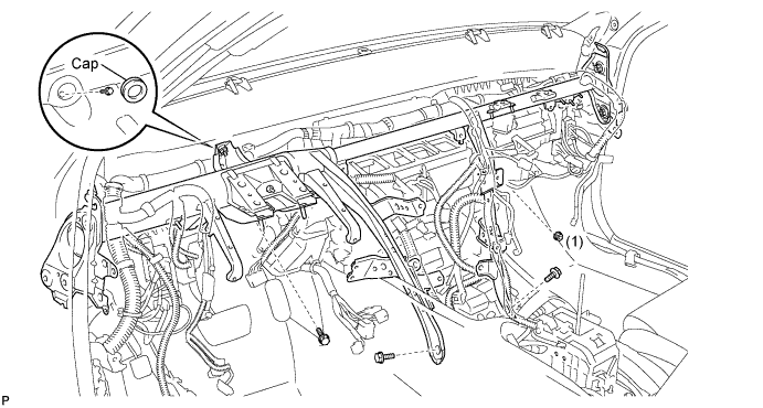
- Torque:
- 9.8 N*m{ 100 kgf*cm , 7 ft.*lbf } (nut 1)
Install the bolt and cap.
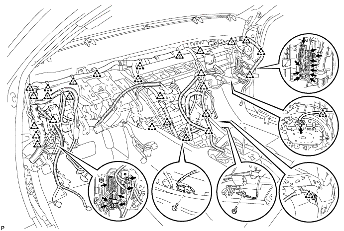
Connect the 19 connectors and attach the 27 clamps.
Install the 2 junction blocks with the 2 bolts and nut.
| 6. INSTALL IMMOBILISER CODE ECU |
| 7. INSTALL DEFROSTER NOZZLE LOWER ASSEMBLY |
Attach the 4 claws to install the defroster nozzle lower.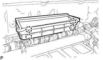
| 8. INSTALL STEERING COLUMN ASSEMBLY (for Manual Tilt) |
Install the steering column assembly with the 4 nuts.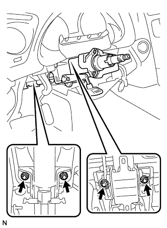
- Torque:
- 21 N*m{ 214 kgf*cm , 16 ft.*lbf }
Connect the connectors and wire harness clamps to the steering column assembly.
Install the clamp to the steering column hole shield.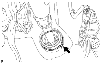
Install the brake pedal return spring.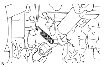
| 9. INSTALL STEERING COLUMN ASSEMBLY (for Power Tilt and Power Telescopic) |
Install the steering column assembly with the 4 nuts.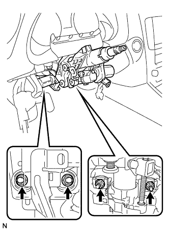
- Torque:
- 26 N*m{ 260 kgf*cm , 19 ft.*lbf }
Connect the connectors and wire harness clamps to the steering column assembly.
Install the clamp to the steering column hole shield.
| 10. INSTALL STEERING SLIDING YOKE SUB-ASSEMBLY |
Align the matchmarks on the No. 2 steering intermediate shaft assembly and steering sliding yoke sub-assembly.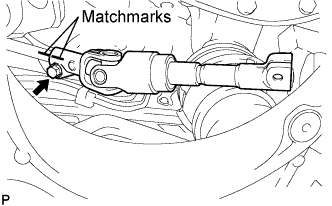
Temporarily install the bolt.
- NOTICE:
- Do not tighten the bolt.
Align the matchmarks on the steering sliding yoke sub-assembly and the power steering gear assembly.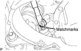
Install bolt (A) and tighten the 2 bolts.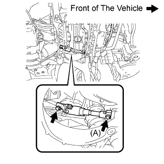
- Torque:
- 35 N*m{ 360 kgf*cm , 26 ft.*lbf }
| 11. INSTALL NO. 1 AIR DUCT |
Engage the 2 claws to install the No. 1 air duct.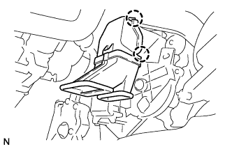
| 12. INSTALL INSTRUMENT PANEL SAFETY PAD ASSEMBLY |
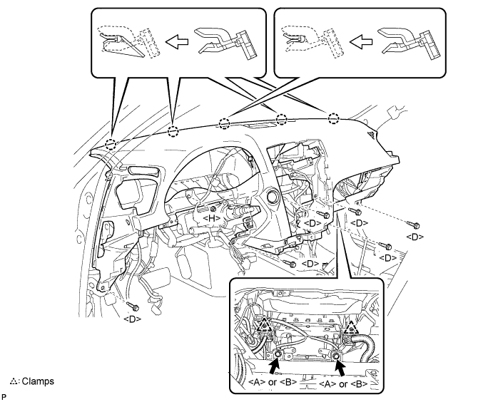
Engage the 5 claws.
- NOTICE:
- Do not allow the wire harness to get caught in the claws.
Engage the 2 clamps.
Install the 2 passenger airbag bolts <A> or <B>.
- Torque:
- 20 N*m{ 204 kgf*cm , 15 ft.*lbf }
Install the 6 bolts <D> and nut <H>.
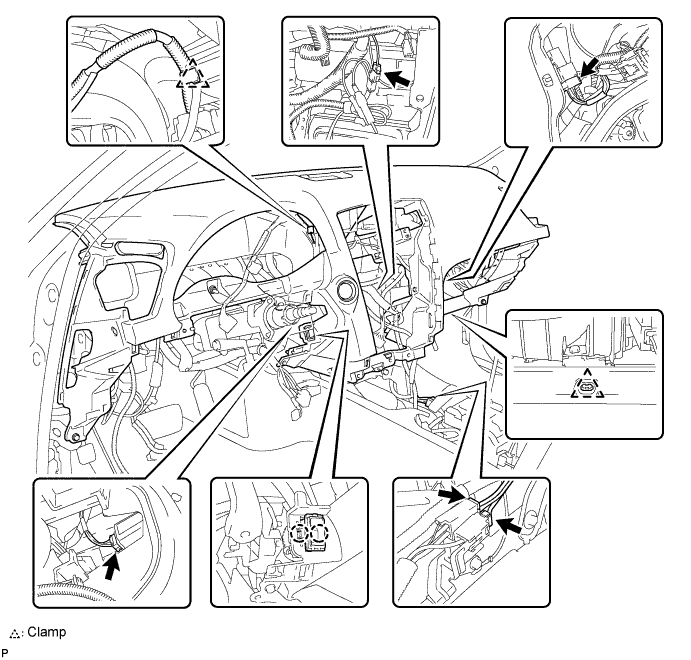
Engage the 2 claws and install the cooler thermistor.
Engage the clamps.
Connect the connectors and install the instrument panel safety pad assembly.
| 13. CONNECT PASSENGER AIRBAG CONNECTOR |
| 14. INSTALL NO. 2 CONSOLE BOX DUCT (for Manual Transmission) |
Install the No. 2 console box duct with the clip.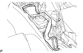
| 15. INSTALL NO. 1 CONSOLE BOX DUCT (for Automatic Transmission) |
Install the No. 1 console box duct with the clip.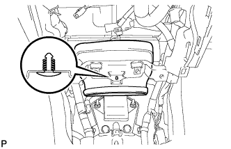
| 16. INSTALL NO. 2 CONSOLE BOX DUCT (for Manual Transmission) |
Install the No. 2 console box duct with the 2 clips.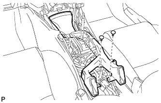
| 17. INSTALL FRONT STEREO COMPONENT SPEAKER ASSEMBLY (w/ Front Center Speaker) |
Connect the connector.
Install the front stereo component speaker assembly with the 2 bolts.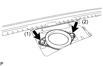
- HINT:
- Install the bolts in the order shown in the illustration.
| 18. INSTALL NO. 3 INSTRUMENT PANEL SPEAKER PANEL SUB-ASSEMBLY |
Engage the 7 claws and install the No. 3 instrument panel speaker panel sub-assembly.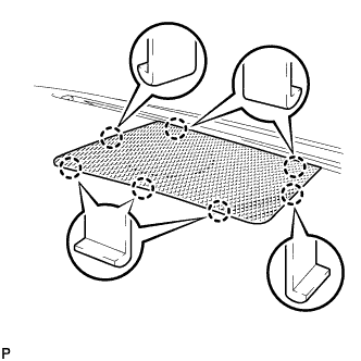
| 19. INSTALL NO. 2 INSTRUMENT PANEL REGISTER ASSEMBLY |
Connect the connector.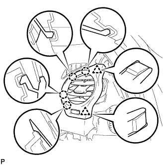
Engage the 4 claws and 2 clips, and install the No. 2 instrument panel register assembly.
| 20. INSTALL NO. 1 INSTRUMENT PANEL REGISTER ASSEMBLY |
Connect the connector.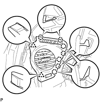
Engage the 7 claws and 2 clips, and install the No. 1 instrument panel register assembly.
| 21. INSTALL FRONT PILLAR GARNISH LH |
Install a new clip <A> on the front pillar garnish LH.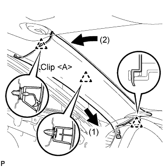
Engage the claw and 2 clips, and install the front pillar garnish LH.
| 22. INSTALL FRONT PILLAR GARNISH RH |
| 23. INSTALL GLOVE COMPARTMENT DOOR ASSEMBLY |
Connect the connectors.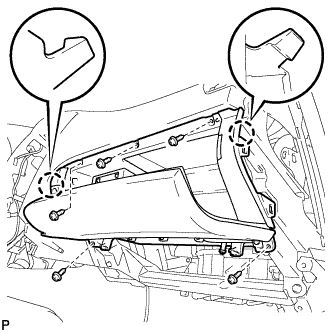
Engage the 2 claws.
Install the glove compartment door assembly with the 5 screws.
| 24. INSTALL FRONT PASSENGER SIDE KNEE AIRBAG ASSEMBLY |
Connect the connector.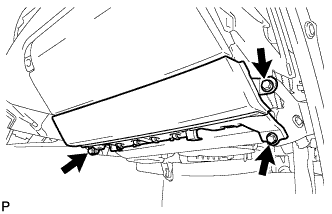
- NOTICE:
- When handling the airbag connector, take care not to damage the airbag wire harness.
Install the front passenger side knee airbag assembly with the 3 bolts.
- Torque:
- 10 N*m{ 102 kgf*cm , 7 ft.*lbf }
| 25. INSTALL NO. 2 INSTRUMENT PANEL UNDER COVER SUB-ASSEMBLY |
Engage the 4 clips and install the No. 2 instrument panel under cover sub-assembly.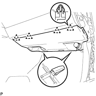
| 26. INSTALL SIDE INSTRUMENT PANEL RH |
Engage the 5 claws and 3 clips, and then install the side instrument panel RH.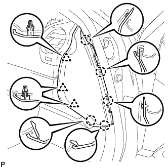
| 27. INSTALL FRONT DOOR OPENING TRIM COVER RH |
Engage the 6 claws and install the front door opening trim cover RH.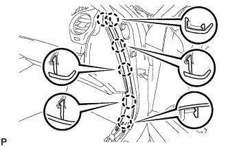
| 28. INSTALL FRONT DOOR SCUFF PLATE RH (w/o Illumination) |
| 29. REMOVE FRONT DOOR SCUFF PLATE RH (w/ Illumination) |
| 30. INSTALL COMBINATION METER ASSEMBLY |
Connect the connectors.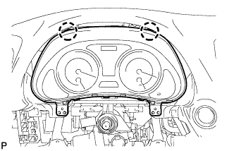
Engage the 2 claws and install the combination meter assembly.
| 31. INSTALL INSTRUMENT CLUSTER FINISH PANEL SUB-ASSEMBLY |
Install the instrument cluster finish panel sub-assembly with the 2 screws and 2 clips.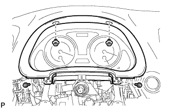
| 32. INSTALL DRIVER SIDE KNEE AIRBAG ASSEMBLY |
Connect the connector.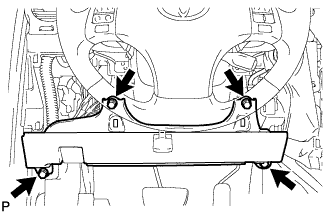
- NOTICE:
- When handling the airbag connector, take care not to damage the airbag wire harness.
Install the driver side knee airbag assembly with the 4 bolts.
- Torque:
- 10 N*m{ 102 kgf*cm , 7 ft.*lbf }
| 33. INSTALL LOWER INSTRUMENT PANEL FINISH PANEL SUB-ASSEMBLY |
Connect the connectors.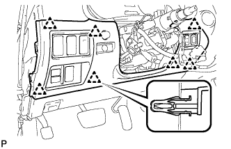
Engage the 7 clips and install the lower instrument panel finish panel sub-assembly.
| 34. INSTALL NO. 1 INSTRUMENT PANEL UNDER COVER SUB-ASSEMBLY |
Connect the connectors.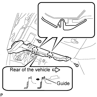
Insert the No. 1 instrument panel under cover sub-assembly into the guide as shown in the illustration.
Engage the 2 claws.
Install the No. 1 instrument panel under cover sub-assembly with the 2 screws <E>.
| 35. INSTALL SIDE INSTRUMENT PANEL LH |
Engage the 5 claws and 3 clips, and then install the side instrument panel LH.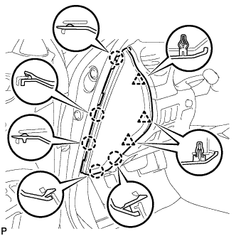
| 36. INSTALL FRONT DOOR OPENING TRIM COVER LH |
Engage the 6 claws and install the front door opening trim cover LH.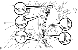
| 37. INSTALL FRONT DOOR SCUFF PLATE LH (w/o Illumination) |
Engage the 4 clips.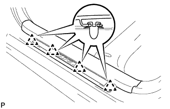
Engage the 7 claws, and install the front door scuff plate LH.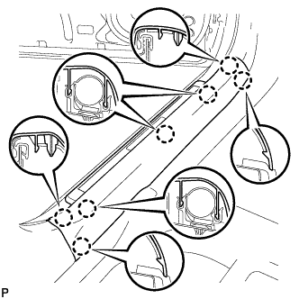
| 38. REMOVE FRONT DOOR SCUFF PLATE LH (w/ Illumination) |
Connect the connector.
Engage the 4 clips.
Engage the 7 claws, and install the front door scuff plate LH.
| 39. INSTALL TURN SIGNAL SWITCH ASSEMBLY WITH SPIRAL CABLE SUB-ASSEMBLY |
Install the turn signal switch assembly with spiral cable sub-assembly to the steering column assembly with the clamp.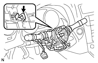
| 40. INSTALL STEERING COLUMN COVER (for Manual Tilt) |
Engage the claw to install the upper steering column cover.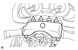
Engage the 4 clips to install the steering column cover upper onto the instrument panel cluster finish panel.
Engage the 2 claws to install the lower steering column cover.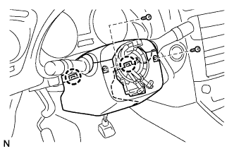
Install the 2 screws.
- Torque:
- 2.0 N*m{ 20 kgf*cm , 18 in.*lbf }
| 41. INSTALL STEERING COLUMN COVER (for Power Tilt and Power Telescopic) |
Engage the claw to install the steering column cover upper.
Engage the 4 clips to install the steering column cover upper onto the instrument panel cluster finish panel.
Engage the 2 claws to install the steering column cover lower.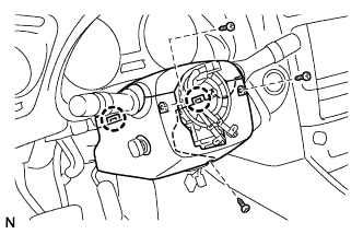
- NOTICE:
- Do not damage the tilt and telescopic switch.
Install the 3 screws.
- Torque:
- 2.0 N*m{ 20 kgf*cm , 18 in.*lbf }
| 42. ADJUST SPIRAL CABLE SUB-ASSEMBLY |
Check that the engine switch is off.
Check that the battery negative (-) terminal is disconnected.
- CAUTION:
- After removing the terminal, wait for at least 90 seconds before starting the operation.
Rotate the spiral cable with steering sensor counterclockwise slowly by hand until it feels firm.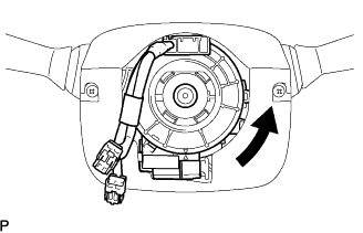
- NOTICE:
- Do not turn the spiral cable with steering sensor by the airbag wire harness.
Rotate the spiral cable with steering sensor clockwise approximately 2.5 turns to align the marks.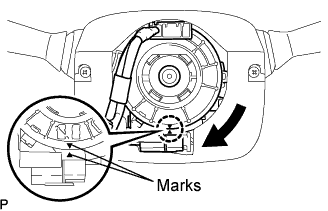
- NOTICE:
- Do not turn the spiral cable with spiral sensor by the airbag wire harness.
- HINT:
- The spiral cable with steering sensor will rotate approximately 2.5 turns to both the left and right from the center.
| 43. INSTALL STEERING WHEEL ASSEMBLY |
Align the matchmarks on the steering wheel assembly and steering main shaft assembly.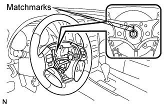
Install the steering wheel assembly set nut.
- Torque:
- 50 N*m{ 510 kgf*cm , 37 ft.*lbf }
| 44. INSTALL STEERING PAD |
Support the steering pad with one hand as shown in the illustration.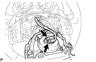
Connect the 2 connectors to the steering pad.
- NOTICE:
- When handling the airbag connector, take care not to damage the airbag wire harness.
Connect the horn connector.
Confirm that the circumference groove of the "torx" screw fits in the screw case, and place the steering pad onto the steering wheel assembly.
Using a "torx" socket wrench (T30), tighten the 2 "torx" screws.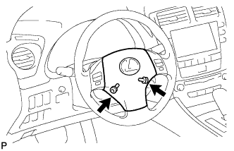
- Torque:
- 8.8 N*m{ 90 kgf*cm , 78 in.*lbf }
| 45. INSTALL LOWER NO. 3 STEERING WHEEL COVER |
Install the steering wheel No.3 cover lower.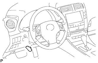
| 46. INSTALL LOWER NO. 2 STEERING WHEEL COVER |
Install the steering wheel No.2 cover lower.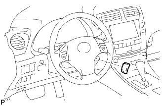
| 47. INSTALL INTEGRATION CONTROL PANEL WITH RADIO RECEIVER ASSEMBLY (w/o Navigation System) |
Connect each connector.
Install the integration control panel w/ radio receiver assembly with the 4 bolts.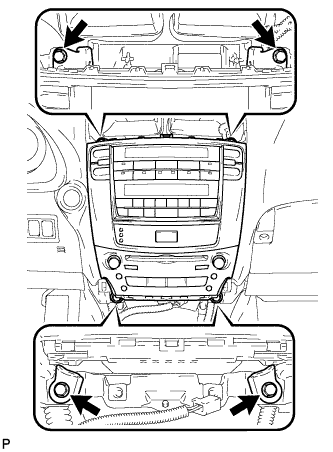
| 48. INSTALL MULTI-DISPLAY WITH RADIO RECEIVER ASSEMBLY (w/ Navigation System) |
Connect each connector.
Install the the multi-display w/ radio receiver assembly with the 4 bolts.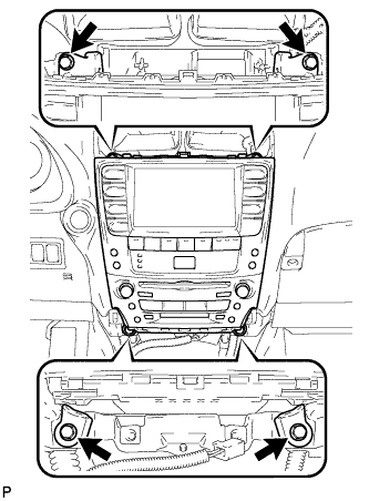
| 49. INSTALL CENTER LOWER INSTRUMENT CLUSTER FINISH PANEL |
Engage the 4 claws and install the center lower instrument cluster finish panel.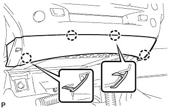
| 50. INSTALL NO. 3 INSTRUMENT PANEL REGISTER ASSEMBLY |
Connect the connectors.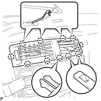
Engage the 11 claws and install the No. 3 instrument panel register assembly.
| 51. INSTALL CONSOLE BOX |
Engage the 2 claws and 2 clips.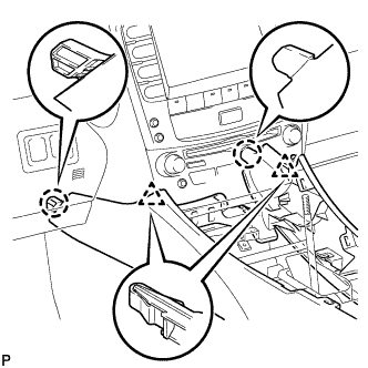
Install the 2 bolts <C>.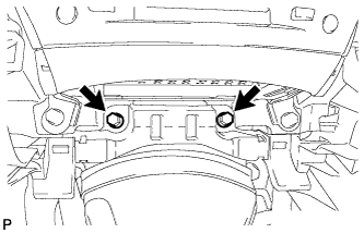
Install the 2 bolts <C>.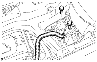
Connect the connector.
Connect the connectors.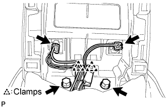
Engage the 2 clamps.
Install the 2 bolts <C>.
| 52. INSTALL CONSOLE BOX REGISTER ASSEMBLY |
Engage the 2 claws and 4 clips, and then install the console box register assembly.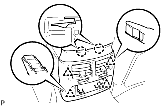
Install the rear ash receptacle assembly.
| 53. INSTALL FRONT ASH RECEPTACLE SUB-ASSEMBLY |
Connect the connectors.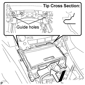
Insert the protruding parts of the front ash receptacle sub-assembly into the 2 guide holes as shown in the illustration.
Install the front ash receptacle sub-assembly with the 2 screws <F>.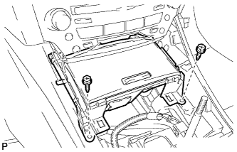
| 54. INSTALL FRONT CONSOLE PANEL SUB-ASSEMBLY (for Manual Transmission) |
Connect the connectors.
Insert the protruding parts of the front ash receptacle sub-assembly into the 2 guide holes as shown in the illustration.
Install the front ash receptacle sub-assembly with the 2 screws <F>.
| 55. INSTALL REAR CONSOLE PANEL SUB-ASSEMBLY (for Manual Transmission) |
Engage the 7 claws and 2 clips.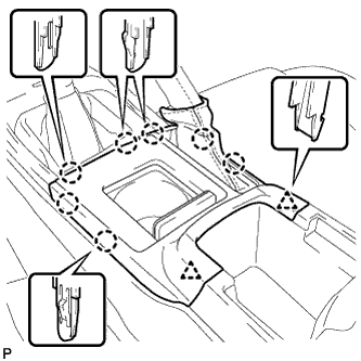
Close the snap.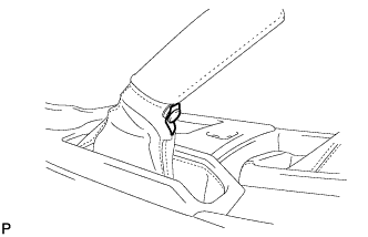
| 56. INSTALL CONSOLE PANEL SUB-ASSEMBLY (for Automatic Transmission) |
Connect the connectors.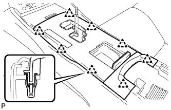
Engage the 8 clips and install the console panel sub-assembly.
| 57. INSTALL UPPER NO. 2 CONSOLE PANEL GARNISH (for Automatic Transmission) |
Engage the claw and 2 clips, and then install the upper No. 2 console panel garnish.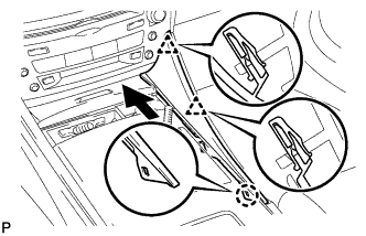
| 58. INSTALL UPPER NO. 1 CONSOLE PANEL GARNISH (for Automatic Transmission) |
Engage the claw and 2 clips, and then install the upper No. 1 console panel garnish.
| 59. INSTALL SHIFT LEVER KNOB SUB-ASSEMBLY (for Manual Transmission) |
| 60. INSTALL SHIFT LEVER KNOB SUB-ASSEMBLY (for Automatic Transmission) |
| 61. INSTALL WINDSHIELD WIPER MOTOR AND LINK ASSEMBLY |
Install the windshield wiper motor and link assembly with the 2 bolts.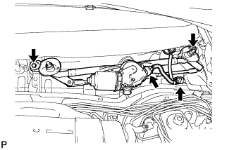
- Torque:
- 5.5 N*m{ 56 kgf*cm , 49 in.*lbf }
Connect the 2 connectors.
| 62. INSTALL COWL TOP VENTILATOR LOUVER SUB-ASSEMBLY |
Engage the 11 claws.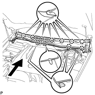
Install the cowl top ventilator louver sub-assembly with the 2 clips.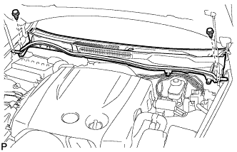
| 63. INSTALL FRONT WIPER ARM AND BLADE ASSEMBLY LH |
Operate the wiper, and stop the windshield wiper motor at the automatic stop position.
Clean the wiper arm serrations.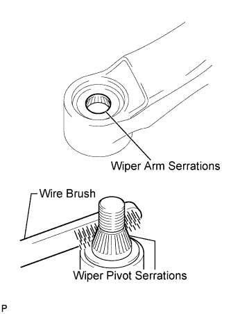
Clean the wiper pivot serrations with a wire brush (when reinstalling).
Install the front wiper arm and blade assembly LH with the nut at the position as shown in the illustration.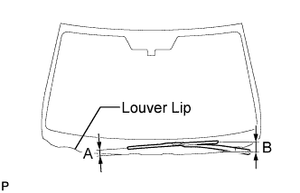
- Torque:
- 22 N*m{ 224 kgf*cm , 16 ft.*lbf }
- HINT:
- Hold the arm hinge by hand to fasten the nut.
Area
Measurement
A
15 to 30 mm (0.59 to 1.18 in.)
B
Approx. 40 mm (1.57 in.)
| 64. INSTALL FRONT WIPER ARM AND BLADE ASSEMBLY RH |
Operate the wiper, and stop the windshield wiper motor at the automatic stop position.
Clean the wiper arm serrations.
Clean the wiper pivot serrations with a wire brush (when reinstalling).
Install the front wiper arm and blade assembly RH with the nut at the position as shown in the illustration.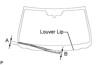
- Torque:
- 22 N*m{ 224 kgf*cm , 16 ft.*lbf }
- HINT:
- Hold the arm hinge by hand to fasten the nut.
Area
Measurement
A
18.5 to 33.5 mm (0.73 to 1.32 in.)
B
Approx. 20 mm (0.79 in.)
Operate the front wipers while spraying washer fluid on the windshield glass. Make sure that the front wipers function properly and there is no interference with the vehicle body.
| 65. INSTALL FRONT WIPER ARM HEAD CAP |
Install the front wiper arm head cap.
- HINT:
- Use the same procedures for the RH side and the LH side.
| 66. INSTALL ROOF DRIP SIDE FINISH MOULDING LH |
| 67. INSTALL ROOF DRIP SIDE FINISH MOULDING RH |
| 68. INSTALL FRONT FENDER PROTECTOR UPPER LH |
Engage the claw and the 3 clips, then install the front upper fender protector LH.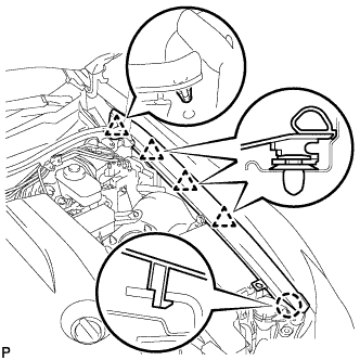
Engage the clip on the rubber portion of the cowl top ventilator louver sub-assembly to the front fender protector upper LH.
| 69. INSTALL FRONT FENDER PROTECTOR UPPER RH |
- HINT:
- Use the same procedures for the RH side and the LH side.
| 70. INSTALL HEATER WATER INLET HOSE |
Install the water hose and attach the clip.
| 71. INSTALL HEATER WATER OUTLET HOSE |
Use the same procedures described for the water hose inlet.
| 72. INSTALL LIQUID TUBE SUB-ASSEMBLY |
Remove the vinyl tape attached to the tube.
Sufficiently apply compressor oil to a new O-ring and the fitting surface of the liquid tube.
- Compressor oil:
- ND-OIL 8 or equivalent
Install the O-ring on the liquid tube.
Install the liquid tube to the fitting hole.
| 73. INSTALL SUCTION PIPE SUB-ASSEMBLY |
Remove the vinyl tape attached to the pipe.
Sufficiently apply compressor oil to a new O-ring and the fitting surface of the suction pipe.
- Compressor oil:
- ND-OIL 8 or equivalent
Install the O-ring on the suction pipe.
Move the hook connector in the direction indicated by the arrow in the illustration.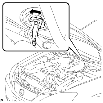
Insert the pipe joints into the fitting holes securely and tighten the bolt.
- Torque:
- 9.8 N*m{ 100 kgf*cm , 7 ft.*lbf }
| 74. CONNECT CABLE TO NEGATIVE BATTERY TERMINAL |
| 75. PERFORM INITIALIZATION |
- NOTICE:
- Some systems need initialization after reconnecting the cable to the negative battery terminal (Click here)
| 76. INSPECT SRS WARNING LIGHT |
| 77. CHARGE REFRIGERANT |
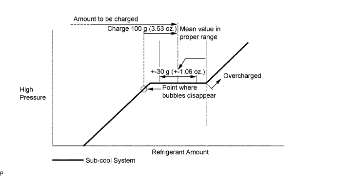
Perform vacuum purging using a vacuum pump.
Charge refrigerant HFC-134a (R134a).
- Standard:
- 430 +- 30 g (15.17 +- 1.06 oz.)
- SST
- 07110-58060
(07117-58060, 07117-58070, 07117-58080, 07117-58090, 07117-78050, 07117-88060, 07117-88070, 07117-88080)
- NOTICE:
- Do not operate the cooler compressor before charging refrigerant as the cooler compressor will not work properly without any refrigerant, and will overheat.
- Do not operate the cooler compressor before charging refrigerant as the cooler compressor will not work properly without any refrigerant, and will overheat.
- Approximately 100 g (3.53 oz.) of refrigerant may need to be charged after bubbles disappear. The refrigerant amount should be checked by measuring its quantity, and not with the sight glass.
- Approximately 100 g (3.53 oz.) of refrigerant may need to be charged after bubbles disappear. The refrigerant amount should be checked by measuring its quantity, and not with the sight glass.
| 78. WARM UP ENGINE |
Warm up the engine at less than 1,850 rpm for 2 minutes or more after charging the refrigerant.
- NOTICE:
- Be sure to warm up the compressor when turning the A/C switch ON after removing and installing the cooler refrigerant lines (including the compressor), to prevent damage to the compressor.
| 79. CHECK FOR LEAKAGE OF REFRIGERANT |
After recharging the refrigerant gas, check for refrigerant gas leakage using a halogen leak detector.
Perform the operation under the following conditions:
- Stop the engine.
- Secure good ventilation (the gas leak detector may react to volatile gases other than refrigerant, such as evaporated gasoline or exhaust gas).
- Repeat the test 2 or 3 times.
- Make sure that some refrigerant remains in the refrigeration system. When compressor is off: approximately 392 to 588 kPa (4 to 6 kgf*cm2 57 to 85 psi)
- Stop the engine.
Using a gas leak detector, check the refrigerant line for leakage.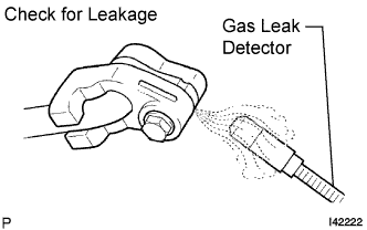
If a gas leak is not detected on the drain hose, remove the blower motor control (blower resistor) from the cooling unit. Insert the gas leak detector sensor into the unit and perform the test.
Disconnect the connector and leave the pressure switch on for approximately 20 minutes. Bring the gas leak detector close to the pressure switch and perform the test.
| 80. INSTALL ENGINE ROOM SIDE COVER LH |
Install the side cover with the 5 clips.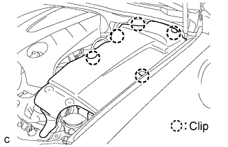
| 81. INSTALL ENGINE ROOM SIDE COVER RH |
Install the side cover with the 2 clips.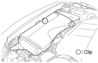
| 82. INSTALL COOL AIR INTAKE DUCT SEAL |
Install the intake duct seal with the 11 clips.