INSTALLATION
Removal / installation
| 1. INSTALL ROOM TEMPERATURE SENSOR |

Install the sensor with the claw.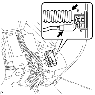

Connect the connector and attach the air hose.
| 2. INSTALL DRIVER SIDE KNEE AIRBAG ASSEMBLY |
Connect the connector.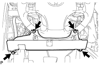
- NOTICE:
- When handling the airbag connector, take care not to damage the airbag wire harness.
Install the driver side knee airbag assembly with the 4 bolts.
- Torque:
- 10 N*m{ 102 kgf*cm , 7 ft.*lbf }
| 3. INSTALL LOWER INSTRUMENT PANEL FINISH PANEL SUB-ASSEMBLY |
Connect the connectors.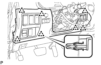
Engage the 7 clips and install the lower instrument panel finish panel sub-assembly.
| 4. INSTALL NO. 1 INSTRUMENT PANEL UNDER COVER SUB-ASSEMBLY |
Connect the connectors.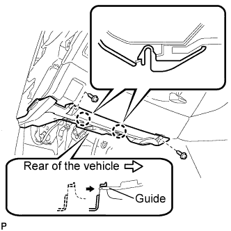
Insert the No. 1 instrument panel under cover sub-assembly into the guide as shown in the illustration.
Engage the 2 claws.
Install the No. 1 instrument panel under cover sub-assembly with the 2 screws <E>.
| 5. INSTALL SIDE INSTRUMENT PANEL LH |
Engage the 5 claws and 3 clips, and then install the side instrument panel LH.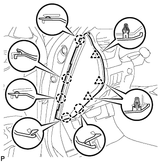
| 6. INSTALL FRONT DOOR OPENING TRIM COVER LH |
Engage the 6 claws and install the front door opening trim cover LH.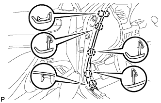
| 7. INSTALL FRONT DOOR SCUFF PLATE LH (w/o Illumination) |
Engage the 4 clips.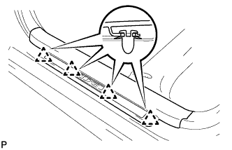
Engage the 7 claws, and install the front door scuff plate LH.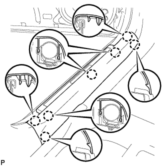
| 8. REMOVE FRONT DOOR SCUFF PLATE LH (w/ Illumination) |
Connect the connector.
Engage the 4 clips.
Engage the 7 claws, and install the front door scuff plate LH.
| 9. CONNECT CABLE TO NEGATIVE BATTERY TERMINAL |
| 10. PERFORM INITIALIZATION |
- NOTICE:
- Some systems need initialization after reconnecting the cable to the negative battery terminal (Click here)
| 11. INSPECT SRS WARNING LIGHT |