REPLACEMENT
Removal / installation
| 1. REMOVE NO. 1 REAR FLOOR PANEL BRACE |

Remove the 4 bolts and rear No. 1 floor panel brace.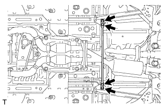

| 2. REMOVE FRONT CENTER FLOOR BRACE |
Remove the 4 bolts and front center floor brace .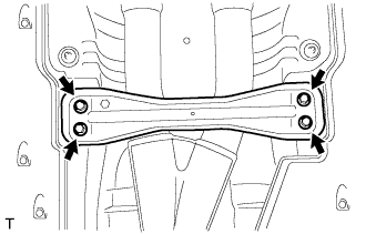
| 3. DISCONNECT HEATED OXYGEN SENSOR |
Remove the grommets of the heated oxygen sensors (BANK 1, BANK 2).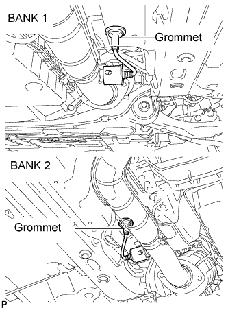
Using the SST, remove a oxygen sensors (BANK 1, BANK 2).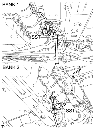
- SST
- 09224-00010
| 4. REMOVE FRONT EXHAUST PIPE ASSEMBLY |
Remove the 4 bolts and 4 nuts.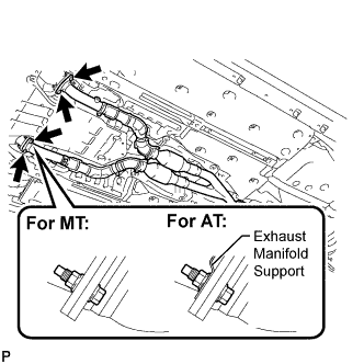
Remove the 2 bolts and 2 compression springs from the tail exhaust pipe assembly.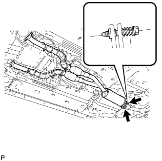
Remove the front exhaust pipe assembly and 3 gaskets.
| 5. DRAIN MANUAL TRANSMISSION OIL |
Remove the drain plug and gasket, and drain the transmission oil.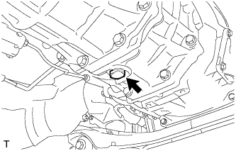
Install a new gasket and the drain plug.
- Torque:
- 37 N*m{ 377 kgf*cm , 27 ft.*lbf }
| 6. REMOVE FRONT FLOOR NO. 1 HEAT INSULATOR |
Remove the 4 nuts and front No. 1 floor heat insulator.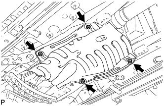
| 7. REMOVE OUTSIDE AIR GUIDE PLATE RH |
Remove the 4 nuts and outside air guide plate RH.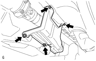
| 8. REMOVE PROPELLER SHAFT WITH CENTER BEARING ASSEMBLY |
Put matchmarks on both flanges.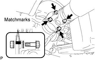
Remove the 4 nuts, bolts and washers.
- HINT:
- If the flange connection is hard to separate, temporarily tighten one nut only and evenly tap the flange with a brass bar and hammer to separate the propeller shaft assembly from the differential companion flange.
Remove the 2 bolts and 2 center support bearing washers. (for automatic transmission)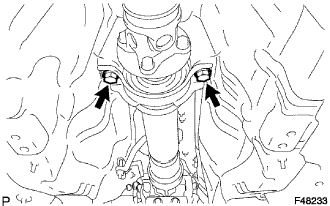
Remove the 2 bolts, 2 center support bearing washers and 2 center support bearing dampers. (for manual transmission)
Separate the center support bearing.
Insert SST in the transmission to prevent oil leakage.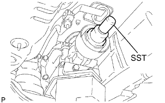
- SST
- 09325-40010
- NOTICE:
- Be careful not to damage the oil seal.
| 9. REMOVE MANUAL TRANSMISSION EXTENSION HOUSING OIL SEAL |
Using SST, remove the oil seal.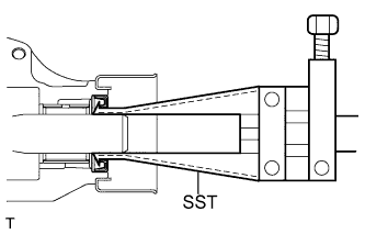
- SST
- 09308-00010
| 10. INSTALL MANUAL TRANSMISSION EXTENSION HOUSING OIL SEAL |
Using SST and a hammer, install a new oil seal to the extension housing.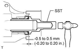
- SST
- 09325-20010
- Installation depth:
- - 0.5 to 0.5 mm (-0.020 to 0.020 in.)
Coat the lip of the oil seal with MP grease.
| 11. INSTALL PROPELLER SHAFT WITH CENTER BEARING ASSEMBLY |
Remove the SST from the transmission.
- SST
- 09325-40010
Insert the yoke of the intermediate shaft into the transmission.
- HINT:
- Be careful not to damage the oil seal.
Install the 2 center support bearing washers and center support bearing. (for automatic transmission)
Install the 2 center support bearing washers, center support bearing and 2 center support bearing dampers. (for manual transmission)
Temporarily tighten the 2 bolts.
Align the matchmarks on the propeller shaft flange and differential companion flange, and connect the shaft with the 4 bolts, washers and nuts.
- Torque:
- 74 N*m{ 750 kgf*cm , 54 ft.*lbf }
Adjust the dimension between the edge surface of the center support bearing and the edge surface of the cushion to 11.5 to 13.5 mm (0.4528 to 0.5315 in.) as shown in illustration.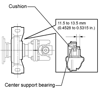
Check that the center line of the bracket is perpendicular to the shaft axial direction.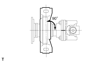
Tighten the 2 bolts.
- Torque:
- 49 N*m{ 500 kgf*cm , 36 ft.*lbf }
| 12. INSPECT AND ADJUST NO. 2 AND NO. 3 JOINT ANGLE |
Stabilize the propeller shaft and differential.
Turn the propeller shaft several times by hand to stabilize the center support bearing.
Check both the No. 2 and No. 3 joint angles.
Using SST, measure the installation angle of the intermediate shaft and propeller shaft.
- SST
- 09370-50010
- HINT:
- The SST should be set directly on the bottom of the shaft.
Using SST, measure the installation angle of the differential.
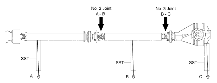
- SST
- 09370-50010
- HINT:
- Measure the installation angle by placing the SST in the positions shown in the illustration.
Calculate the No. 2 joint angle.
- No. 2 joint angle:
- A - B = -1°13' to -0°13'
- A:
- Intermediate shaft installation angle
- B:
- Propeller shaft installation angle
Calculate the No. 3 joint angle.
- No. 3 joint angle:
- B - C = 1°30' to 2°30'
- B:
- Propeller shaft installation angle
- C:
- Differential installation angle
- HINT:
- If the measured angle is not within the specified range, adjust it with the center support bearing washers.
Adjust the No. 2 joint angle .
Select the center support bearing washers for adjustment.
Adjustment washer (for manual transmission) Thickness mm (in)
2 (0.078)
4.5 (0.1772)
6.5 (0.2559)
9.0 (0.3543)
11 (0.4331)
Adjustment washer (for automatic transmission) Thickness mm (in)
2 (0.078)
4.5 (0.1772)
6.5 (0.2559)
9.0 (0.3543)
11 (0.4331)
13.5 (0.5315)
- NOTICE:
- The 2 washers should be the same thickness.
| 13. INSTALL OUTSIDE AIR GUIDE PLATE RH |
Install the air guide plate outside RH with the 4 nuts.
- Torque:
- 5.4 N*m{ 55 kgf*cm , 48 in.*lbf }
| 14. INSTALL FRONT FLOOR NO. 1 HEAT INSULATOR |
Install the No. 1 heat insulator with the 4 nuts.
- Torque:
- 5.4 N*m{ 55 kgf*cm , 48 in.*lbf }
| 15. INSTALL FRONT EXHAUST PIPE ASSEMBLY |
Using a vernier caliper, measure the free length of the compression springs.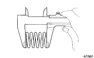
- Minimum length:
- 38.5 mm (1.516 in.)
Install a new gasket to the rear end of the front exhaust pipe.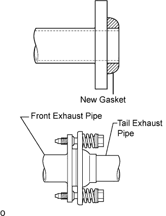
- NOTICE:
- Be careful with the installation direction of the gasket.
- Be careful with the installation direction of the gasket.
- Do not reuse the gasket.
- Do not reuse the gasket.
- To ensure a proper seal, do not use the tail exhaust pipe to force the gasket onto the front exhaust pipe.
- HINT:
- Using a plastic hammer, uniformly strike the gasket so that the gasket and front exhaust pipe are properly fit.
- To ensure a proper seal, do not use the tail exhaust pipe to force the gasket onto the front exhaust pipe.
Install 3 new gaskets and front exhaust pipe assembly.
- CAUTION:
- Do not reuse the gaskets.
Install the 2 bolts and 2 compression springs.
- Torque:
- 43 N*m{ 438 kgf*cm , 32 ft.*lbf }
Install 4 new nuts and 4 bolts.
- Torque:
- 62 N*m{ 632 kgf*cm , 46 ft.*lbf }
- NOTICE:
- Do not reuse the nuts.
| 16. INSTALL HEATED OXYGEN SENSOR |
Before installing the heated oxygen sensors, twist the sensor wires counterclockwise 4 turns.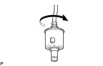
Using the SST, install the heated oxygen sensors to the front exhaust pipe.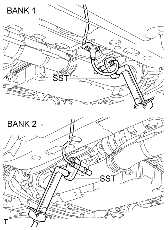
- SST
- 09224-00010
- Torque:
- 44 N*m{ 449 kgf*cm , 33 ft.*lbf }
After installing the sensors, check that the sensor wires are not twisted.
If the sensor wires are twisted, reinstall them.
Install the grommets of the heated oxygen sensors.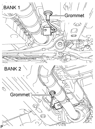
| 17. INSTALL FRONT CENTER FLOOR BRACE |
Install the front center floor brace with the 4 bolts.
- Torque:
- 7.4 N*m{ 75 kgf*cm , 65 in.*lbf }
| 18. INSTALL NO. 1 REAR FLOOR PANEL BRACE |
Install the rear No. 1 floor panel brace with the 4 bolts.
- Torque:
- 19 N*m{ 194 kgf*cm , 14 ft.*lbf }
| 19. ADD MANUAL TRANSMISSION OIL |
Park the vehicle in a level place.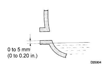
Remove the transmission filler plug and gasket.
Check that the oil surface is within 5 mm (0.20 in.) below the lowest point of the transmission filler plug opening.
- Oil grade:
- API GL-4 or GL-5
- Viscosity:
- SAE 75W-90
- NOTICE:
- Problems may occur when the oil level is too high or too low.
- After replacing the oil, drive the vehicle and check the oil level again.
- Problems may occur when the oil level is too high or too low.
Check for oil leakage if the oil level is low.
Install the transmission filler plug and a new gasket.
- Torque:
- 37 N*m{ 377 kgf*cm , 27 ft.*lbf }
| 20. CHECK FOR EXHAUST GAS LEAKS |
| 21. INSPECT AND ADJUST MANUAL TRANSMISSION OIL LEVEL |
Park the vehicle on a level surface.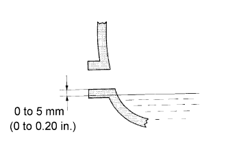
Remove the transmission filler plug and gasket.
Check that the oil surface is within 5 mm (0.20 in.) of the lowest point of the transmission filler plug opening.
- NOTICE:
- Problems may occur if the oil level is too high or low.
- After replacing the oil, drive the vehicle and check the oil level again.
- Problems may occur if the oil level is too high or low.
Check for oil leakage when the oil level is low.
Install the transmission filler plug and a new gasket.
- Torque:
- 37 N*m{ 377 kgf*cm , 27 ft.*lbf }