INSTALLATION
Removal / installation
| 1. INSTALL HEADLIGHT DIMMER SWITCH ASSEMBLY |

Install the headlight dimmer switch assembly as shown in the illustration.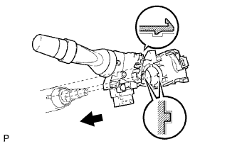

Install the headlight dimmer switch assembly with the claw and the clamp.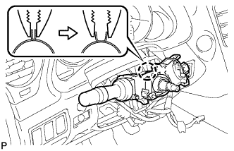
Connect the connector.
| 2. INSTALL WINDSHIELD WIPER SWITCH ASSEMBLY |
Engage the claw and install the windshield wiper switch assembly as shown in the illustration.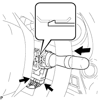
Connect the 2 connectors.
| 3. INSTALL SPIRAL CABLE WITH STEERING ANGLE SENSOR |
Check that the front wheels are facing straight ahead.
Set the turn signal switch to the neutral position.
- NOTICE:
- If it is not in the neutral position, the pin of the turn signal switch may be snapped.
Engage the 3 claws and install the spiral cable with steering sensor.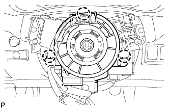
- NOTICE:
- When replacing the spiral cable with a new one, remove the lock pin before installing the steering wheel assembly.
Connect the connectors to the spiral cable with steering sensor.
- NOTICE:
- When handling the airbag connector, take care not to damage the airbag wire harness.
| 4. INSTALL STEERING COLUMN COVER (for Manual Tilt and Telescopic) |
Engage the claw to install the upper steering column cover.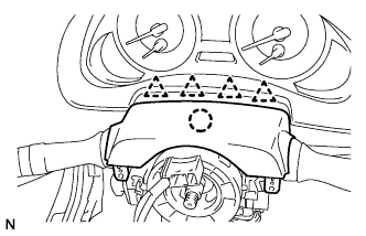
Engage the 4 clips to install the steering column cover upper onto the instrument panel cluster finish panel.
Engage the 2 claws to install the lower steering column cover.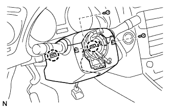
Install the 2 screws.
- Torque:
- 2.0 N*m{ 20 kgf*cm , 18 in.*lbf }
| 5. INSTALL STEERING COLUMN COVER (for Power Tilt and Power Telescopic) |
Engage the claw to install the steering column cover upper.
Engage the 4 clips to install the steering column cover upper onto the instrument panel cluster finish panel.
Engage the 2 claws to install the steering column cover lower.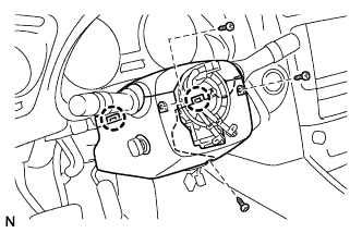
- NOTICE:
- Do not damage the tilt and telescopic switch.
Install the 3 screws.
- Torque:
- 2.0 N*m{ 20 kgf*cm , 18 in.*lbf }
| 6. INSTALL STEERING WHEEL ASSEMBLY |
For Power Tilt and Power Telescopic (Click here)
| 7. INSTALL STEERING PAD |
Support the steering pad with one hand as shown in the illustration.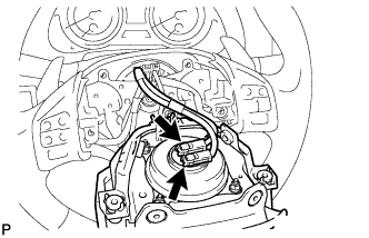
Connect the 2 connectors to the steering pad.
- NOTICE:
- When handling the airbag connector, take care not to damage the airbag wire harness.
Connect the horn connector.
Confirm that the circumference groove of the "torx" screw fits in the screw case, and place the steering pad onto the steering wheel assembly.
Using a "torx" socket wrench (T30), tighten the 2 "torx" screws.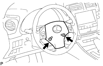
- Torque:
- 8.8 N*m{ 90 kgf*cm , 78 in.*lbf }
| 8. INSTALL NO. 3 LOWER STEERING WHEEL COVER |
Install the steering wheel No.3 cover lower.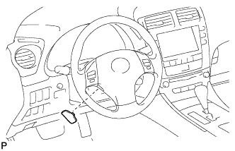
| 9. INSTALL NO. 2 LOWER STEERING WHEEL COVER |
Install the steering wheel No.2 cover lower.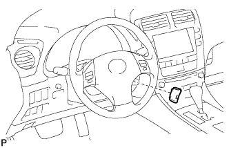
| 10. CONNECT CABLE TO NEGATIVE BATTERY TERMINAL |
| 11. PERFORM INITIALIZATION |
| 12. INSPECT SRS WARNING LIGHT |