REASSEMBLY
Removal / installation
| 1. INSTALL SHIFT ARM |

Install the shift arm and shift arm pivot onto the shift interlock bracket.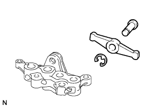

Install a new E-ring onto the shift arm pivot.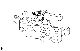
| 2. INSTALL NO. 4 GEAR SHIFT FORK SHAFT |
Install the spring and ball into the shift interlock bracket.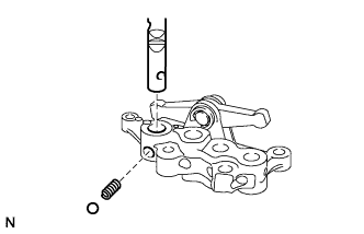
Install the No. 4 gear shift fork shaft.
| 3. INSTALL NO. 4 GEAR SHIFT FORK |
Install the No. 4 gear shift fork onto the No. 4 gear shift fork shaft.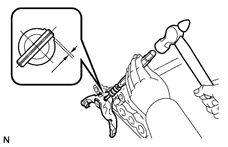
Using a pin punch (5 mm (0.20 in.)) and hammer, tap a new slotted spring pin to install the No. 4 shift fork and No. 4 gear shift fork shaft.
- Installation depth:
- 0 to 0.5 mm (0 to 0.020 in.)
| 4. INSTALL NO. 1 GEAR SHIFT FORK |
Install the No. 1 gear shift fork and No. 2 gear shift head onto the No. 4 gear shift fork shaft.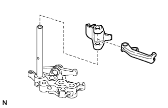
Using a pin punch (5 mm (0.20 in.)) and hammer, tap a new slotted spring pin to install the No. 2 gear shift head and No. 4 gear shift fork shaft.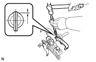
- Installation depth:
- 0 to 0.5 mm (0 to 0.020 in.)
| 5. INSTALL NO. 3 GEAR SHIFT FORK SHAFT |
Apply MP grease to the No. 1 shift interlock pin and install it onto the shift interlock bracket.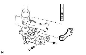
Install the spring and ball onto the shift interlock bracket.
Install the No. 3 gear shift head and No. 3 gear shift fork shaft into the shift interlock bracket.
- HINT:
- Place the No. 4 gear shift fork shaft in the neutral position.
| 6. INSTALL NO. 3 GEAR SHIFT HEAD |
Using a pin punch (5 mm (0.20 in.)) and hammer, tap a new slotted spring pin to install the No. 3 gear shift head and No. 3 gear shift fork shaft.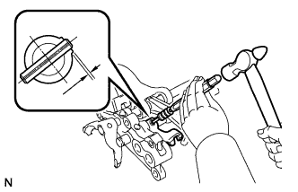
- Installation depth:
- 0 to 0.5 mm (0 to 0.020 in.)
| 7. INSTALL NO. 2 GEAR SHIFT FORK SHAFT |
Apply MP grease to the No. 2 and No. 3 shift interlock pins, then install them into the shift interlock bracket.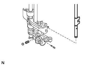
Install the spring and ball into the shift interlock bracket.
Install the No. 2 gear shift fork shaft onto the shift interlock bracket.
- HINT:
- Place the No. 3 and No. 4 gear shift fork shafts in the neutral position.
| 8. INSTALL NO. 2 GEAR SHIFT FORK |
Install the No. 2 gear shift fork with the bolt.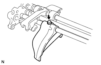
- Torque:
- 20 N*m{ 200 kgf*cm , 14 ft.*lbf }
| 9. INSTALL NO. 1 GEAR SHIFT FORK SHAFT |
Apply MP grease to the No. 2 and No. 3 shift interlock pins, then install them into the shift interlock bracket.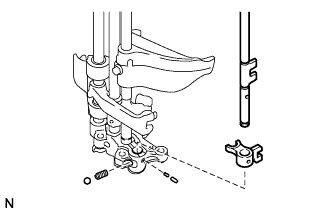
Install the spring and ball into the shift interlock bracket.
Install the No. 1 gear shift head and No. 1 gear shift fork shaft onto the shift interlock bracket.
- HINT:
- Place the No. 4, No. 3 and No. 2 gear shift fork shafts in the neutral position.
| 10. INSTALL NO. 1 GEAR SHIFT HEAD |
Using a pin punch (5 mm (0.20 in.)) and hammer, tap a new slotted spring pin to install the No. 1 gear shift head and No. 1 gear shift fork shaft.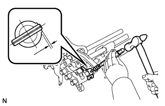
- Installation depth:
- 0 to 0.5 mm (0 to 0.020 in.)
| 11. INSTALL NO. 3 GEAR SHIFT FORK |
Install the No. 3 gear shift fork with the bolt.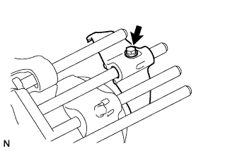
- Torque:
- 20 N*m{ 200 kgf*cm , 14 ft.*lbf }
Install 4 new snap rings.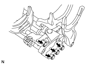
| 12. INSTALL TRANSMISSION CASE OIL SEAL |
Using SST and a hammer, tap a new oil seal into the front case in accordance with the dimension specified in the illustration.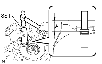
- SST
- 09950-70010
(09951-07100)
09950-60010 (09951-00470)
- Dimension A:
- 60.0 to 60.8 mm (2.362 to 2.394 in.)
Apply gear oil to the lip of the oil seal.
| 13. INSTALL FRONT BEARING SHAFT SNAP RING |
Using snap ring pliers, install the 2 snap rings.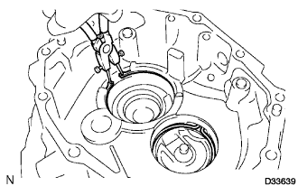
| 14. INSTALL NO. 1 OIL RECEIVER PIPE |
Install the No. 1 oil receiver pipe onto the transmission front case.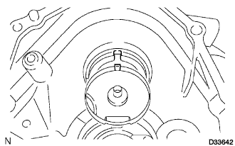
- HINT:
- Align the convex portion of the oil receiver pipe with the cutout of the front case and install the oil receiver pipe onto the front case.
| 15. INSTALL TRANSMISSION FRONT CASE |
Apply gear oil to all sliding and rotating parts.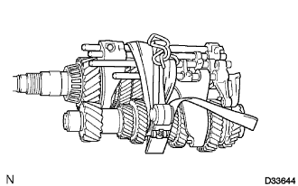
Provisionally install the output shaft, input shaft, counter gear shaft and control assembly, and tie them with a rope or string.
Using a snap ring expander, extend the 2 snap rings and install the output shaft, input shaft, counter gear shaft and control assembly.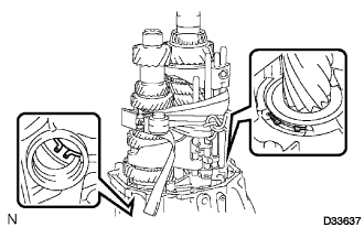
- HINT:
- Make sure that the snap ring is fully engaged into the grooves of the input shaft and front bearing of the counter gear shaft.
Untie the output shaft, input shaft, counter gear shaft and control assembly.
Using a hexagonal wrench (24 mm), install the plug onto the front case.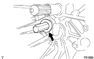
- Torque:
- 39 N*m{ 400 kgf*cm , 29 ft.*lbf }
Install the 4 bolts onto the shift interlock bracket.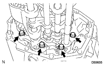
- Torque:
- 21 N*m{ 214 kgf*cm , 15 ft.*lbf }
| 16. INSTALL REVERSE IDLER GEAR |
Install the reverse idler gear, reverse idler gear bearing and reverse idler gear shaft.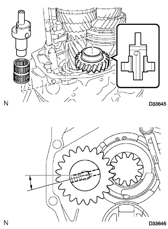
- HINT:
- Make sure that the reverse idler gear faces the correct direction as shown in the illustration.
- NOTICE:
- Make sure that the tapped hole portion of the reverse idler shaft is in the position shown in the illustration.
| 17. INSTALL SHIFT AND SELECT LEVER CAM |
Install the shift and select lever cam onto the shaft and install a new E-ring.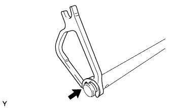
| 18. INSTALL SHIFT AND SELECT LEVER |
Install the lock ball pin and spring into the shift and select lever.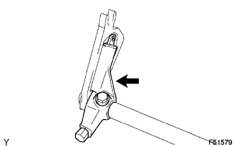
Install the shift and select lever onto the shift and select lever shaft.
Install a new bolt onto the shift and select lever.
- Torque:
- 33 N*m{ 340 kgf*cm , 25 ft.*lbf }
| 19. INSTALL SHIFT AND SELECT LEVER SHAFT |
Align the groove of the shift and select cam with the reverse idler gear shaft, and the claw with the groove of the control assembly, and install them.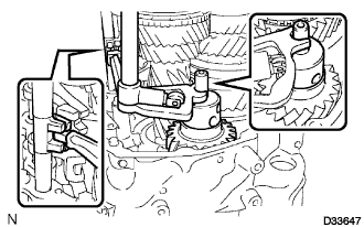
| 20. INSTALL TRANSMISSION MIDDLE CASE BEARING |
Using SST and a press, install the transmission middle case bearing to the transmission middle case.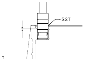
- SST
- 09950-60010
(09951-00230)
- Installation depth:
- 0.5 to 1.5 mm (0.0197 to 0.0591 in.)
| 21. INSTALL NO. 2 OIL RECEIVER PIPE |
Install the No. 2 oil receiver pipe into the transmission middle case.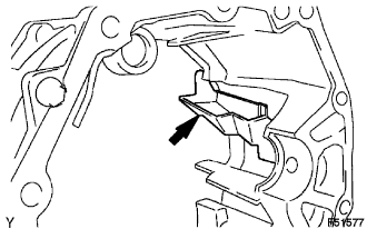
| 22. INSTALL TRANSMISSION DRAIN PLUG |
Install the drain plug with a new gasket onto the transmission middle case.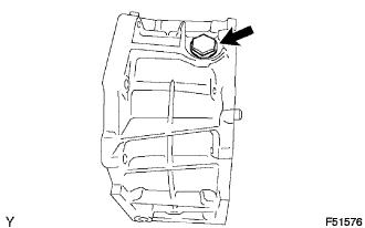
- Torque:
- 37 N*m{ 377 kgf*cm , 27 ft.*lbf }
| 23. INSTALL TRANSMISSION MIDDLE CASE |
Clean the seal packing attached on the transmission middle case and transmission front case using a scraper and wire brush. Then remove the oil with non-residue type solvent or equivalent.
- NOTICE:
- Do not scratch the fitting surface.
Apply FIPG to the transmission middle case, as shown in the illustration.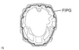
- FIPG:
- Part No. 08826-00090, THREE BOND 1281 or equivalent
- NOTICE:
- Parts must be assembled within 10 minutes of application. Otherwise, the packing (FIPG) material must be removed and reapplied.
Install the transmission middle case with the 11 bolts onto the transmission front case.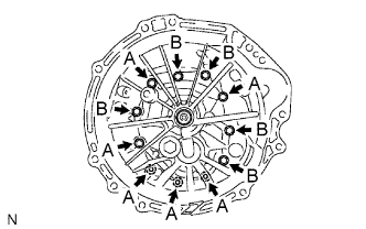
- Torque:
- 40 N*m{ 408 kgf*cm , 30 ft.*lbf }
- Bolt length:
- Bolt A:
- 40 mm (1.57 in.)
- Bolt B:
- 80 mm (3.15 in.)
| 24. INSTALL REVERSE IDLER GEAR SHAFT BOLT |
Install a new gasket and the reverse idler gear shaft bolt onto the reverse idler gear shaft.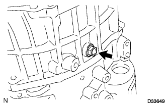
- Torque:
- 28 N*m{ 286 kgf*cm , 21 ft.*lbf }
| 25. INSTALL TRANSMISSION OIL SEPARATOR |
Install the transmission oil separator with the 2 bolts.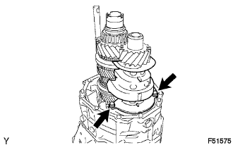
- Torque:
- 8.5 N*m{ 87 kgf*cm , 75 in.*lbf }
| 26. INSTALL TRANSMISSION REAR CASE BEARING |
Using SST and a press, install the transmission rear case bearing to the transmission rear case.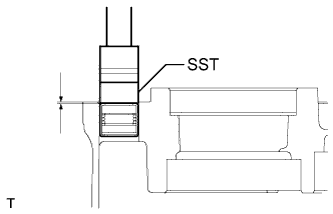
- SST
- 09950-60010
(09951-00230)
- Installation depth:
- 1.0 to 2.0 mm (0.0394 to 0.0787 in.)
| 27. INSTALL COUNTER GEAR REAR CYLINDRICAL ROLLER BEARING |
Coat a new counter gear rear cylindrical roller bearing with gear oil, and using SST and a press, install it into the transmission rear case.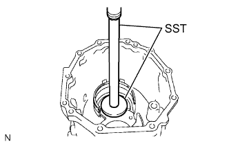
- SST
- 09950-70010
(09951-07360)
09950-60010 (09951-00650)
Install the bearing lock plate with the bolt.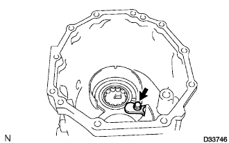
- Torque:
- 11 N*m{ 115 kgf*cm , 8.3 ft.*lbf }
| 28. INSTALL OUTPUT SHAFT REAR BEARING OUTER RACE |
Using SST and a press, press in 2 new bearing outer races.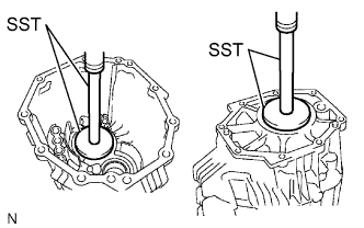
- SST
- 09950-70010
(09951-07100, 09951-07360)
09950-60020 (09951-00790)
| 29. INSTALL OIL SEPARATOR PACKING SEAL |
Install the oil separator packing seal onto the transmission rear case.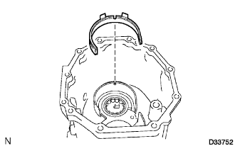
- HINT:
- Insert the protruding part of the oil separator packing seal into the groove on the transmission rear case.
| 30. INSTALL EXTENSION HOUSING OIL RECEIVER PIPE |
Install the extension housing oil receiver pipe onto the transmission rear case.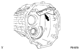
| 31. INSTALL MANUAL TRANSMISSION FILLER PLUG |
Install the 2 transmission filler plugs with 2 new gaskets onto the transmission rear case.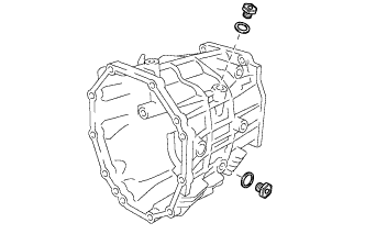
- Torque:
- 37 N*m{ 377 kgf*cm , 27 ft.*lbf }
| 32. INSTALL TRANSMISSION REAR CASE |
Clean the seal packing attached on the transmission rear case and transmission middle case using a scraper and wire brush. Then remove the oil with non-residue type solvent or equivalent.
- NOTICE:
- Do not scratch the fitting surface.
Apply FIPG to the transmission rear case, as shown in the illustration.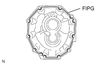
- FIPG:
- Part No. 08826-00090, THREE BOND 1281 or equivalent
- NOTICE:
- Parts must be assembled within 10 minutes of application. Otherwise, the packing (FIPG) material must be removed and reapplied.
Install the transmission rear case with the 10 bolts and bracket onto the transmission middle case.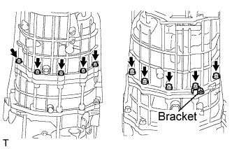
- Torque:
- 40 N*m{ 408 kgf*cm , 30 ft.*lbf }
| 33. INSTALL SHIFT DETENT BALL PLUG |
Install the ball and compression spring onto the transmission rear case.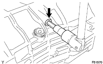
Install a new shift detent ball plug onto the transmission rear case.
- Torque:
- 25 N*m{ 250 kgf*cm , 18 ft.*lbf }
| 34. INSTALL OUTPUT SHAFT ADJUST NUT |
Using a belt and wooden block, fasten the transmission to the workbench.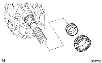
Install a new spacer and a new No. 2 taper roller bearing.
Using SST, provisionally tighten a new nut until there is no slack in the output shaft.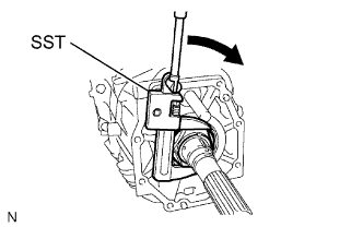
- SST
- 09922-10010
- HINT:
- No preload should be applied to the nut.
Fit the bearing into the output shaft by turning the output shaft 15 times.
Place the gearshift into 5th gear and check the initial torque of the input shaft.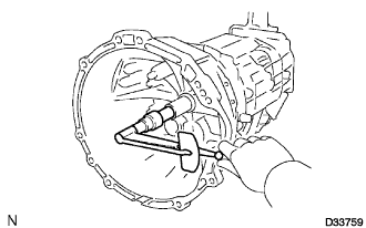
Using SST, tighten the nut.
- SST
- 09922-10010
Place the gearshift into 5th gear and check the initial torque of the input shaft.
Confirm that the difference between (d) and (f) is within the specified values.
- Preload (at starting):
- 0.45 to 1.35 N*m (4.59 to 13.77 kgf*cm, 3.98 to 11.95 in.*lbf)
- NOTICE:
- If the output shaft adjusting nut is loose or removed due to a large preload, always replace the spacer with a new one.
Using a chisel and hammer, stake the output shaft adjust nut.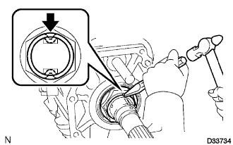
| 35. INSTALL EXTENSION HOUSING OIL RECEIVER PIPE |
Install the oil receiver pipe.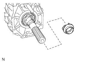
Using a snap ring expander, install the snap ring.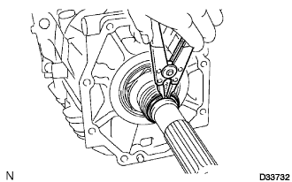
| 36. INSTALL MANUAL TRANSMISSION EXTENSION HOUSING OIL SEAL |
Using SST and a hammer, install a new oil seal into the extension housing in accordance with the dimension specified in the illustration.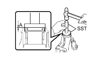
- SST
- 09950-60020
(09951-00640)
09950-70010 (09951-07100)
- Dimension A:
- -0.5 to 0.5 mm (-00.197 to 0.0197 in.)
Apply gear oil to the lip of the oil seal.
| 37. INSTALL EXTENSION HOUSING REAR OIL SEAL |
Using SST and a hammer, install a new extension housing rear oil seal.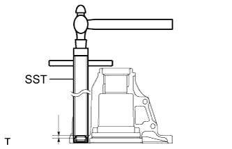
- SST
- 09612-70100
(09612-07210)
- Installation depth:
- 4.6 to 5.4 mm (0.1811 to 0.2126 in.)
| 38. INSTALL EXTENSION HOUSING DUST DEFLECTOR |
Using a plastic hammer, install a new extension housing dust deflector.
| 39. INSTALL EXTENSION HOUSING SUB-ASSEMBLY |
Clean the seal packing attached on the transmission middle case and extension housing using a scraper and wire brush. Then remove the oil with non-residue type solvent or equivalent.
- NOTICE:
- Do not scratch the fitting surface.
Apply FIPG to the extension housing, as shown in the illustration.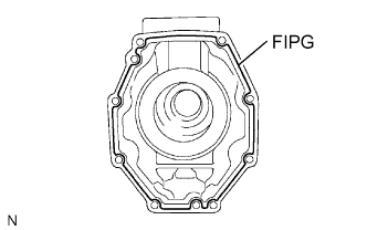
- FIPG:
- Part No. 08826-00090, THREE BOND 1281 or equivalent
- NOTICE:
- Parts must be assembled within 10 minutes of application. Otherwise, the packing (FIPG) material must be removed and reapplied.
Install the extension housing with the 8 bolts.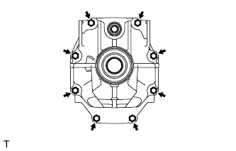
- Torque:
- 29 N*m{ 296 kgf*cm , 21 ft.*lbf }
| 40. INSTALL FLOOR SHIFT CONTROL SHAFT |
Install the control shaft collar onto the shift and select lever.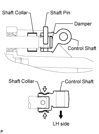
Install the shift lever damper onto the floor shift control shaft, align the holes to allow the pin to be installed to the floor shift control shaft and shift and select lever shaft, and insert the shaft pin from above.
Install the shaft collar to the floor shift control shaft, and stake the both sides.
- NOTICE:
- Be careful to install the floor shift control shaft in the proper direction.
| 41. INSTALL CONTROL SHAFT |
Install the 2 collars to the floor shift control shaft.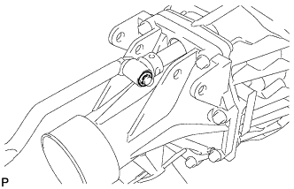
Install the control shaft with a new E-ring.
| 42. INSTALL SHIFT LEVER RETAINER BUSHING |
Install the 4 shift lever bushings.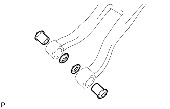
| 43. INSTALL FLOOR SHIFT CONTROL SHIFT LEVER RETAINER |
Install the floor shift control shift lever retainer with the 2 shift lever pins.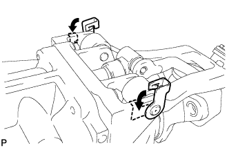
Secure the shift lever pins to the extension housing.
| 44. INSTALL SHIFT AND SELECT LEVER BOOT |
Install the shift and select lever boot.
| 45. INSTALL FLOOR SHIFT CONTROL SHIFT LEVER RETAINER SUB-ASSEMBLY |
Install the floor shift lever retainer sub-assembly to the control shift lever retainer in accordance with the dimension specified in the illustration.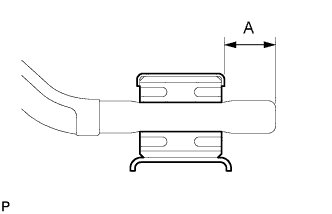
- Dimension A:
- 18 mm (0.7087 in.)
| 46. INSTALL BACK-UP LIGHT SWITCH ASSEMBLY |
Using SST, install the back-up light switch with a new gasket onto the transmission middle case.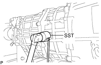
- SST
- 09817-16011
- Torque:
- 44 N*m{ 450 kgf*cm , 33 ft.*lbf }
Install the wire harness with the clamp and bolt.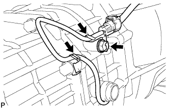
- Torque:
- 13 N*m{ 130 kgf*cm , 9 ft.*lbf }