REASSEMBLY
Removal / installation
| 1. INSTALL INPUT SHAFT FRONT BEARING |

Using SST and a press, install the input shaft front bearing onto the input shaft.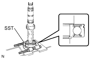

- SST
- 09950-00020
- HINT:
- Make sure that the groove of the bearing faces the correct direction as shown in the illustration.
| 2. INSTALL INPUT SHAFT FRONT BEARING SNAP RING |
Select a snap ring that will allow minimum axial play.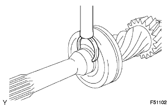
- Standard clearance:
- 0.1 mm (0.004 in.) or less
- Snap ring thickness:
Part No.
Thickness: mm (in.)
Mark
90520-31026
2.65 to 2.70
(0.1043 to 0.1063)
A
90520-31027
2.70 to 2.75
(0.1063 to 0.1083)
B
90520-31028
2.75 to 2.80
(0.1083 to 0.1102)
C
90520-31029
2.80 to 2.85
(0.1102 to 0.1122)
D
90520-31030
2.85 to 2.90
(0.1122 to 0.1142)
E
90520-31031
2.90 to 2.95
(0.1142 to 0.1161)
F
Using a brass bar and hammer, install the snap ring onto the input shaft.
| 3. INSTALL NO. 2 TRANSMISSION CLUTCH HUB |
Apply a light coat of gear oil to the sleeve and hub.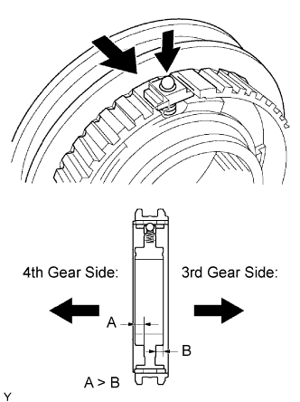
Install the clutch hub sleeve onto the No. 2 transmission clutch hub.
Install the 3 shifting keys, 3 shifting key springs and 3 balls onto the clutch hub.
- NOTICE:
- Take care to prevent the ball from flying off.
- HINT:
- Make sure that the No. 2 transmission clutch hub faces the correct direction as shown in the illustration.
| 4. INSTALL NO. 3 TRANSMISSION CLUTCH HUB |
Apply a light coat of gear oil to the sleeve and hub.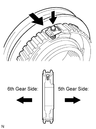
Install the clutch hub sleeve onto the No. 3 transmission clutch hub.
Install the 3 shifting keys, 3 shifting key springs and 3 balls onto the clutch hub.
- NOTICE:
- Take care to prevent the ball from flying off.
- HINT:
- Make sure that the No. 2 transmission clutch hub faces the correct direction as shown in the illustration.
| 5. INSTALL 4TH GEAR NEEDLE ROLLER BEARING |
Coat the 4th gear needle roller bearing with gear oil, then install it onto the input shaft.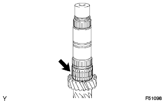
| 6. INSTALL 4TH GEAR |
Coat the 4th gear and No. 3 synchronizer ring with gear oil, then install them onto the input shaft.
Using SST and a press, install the No. 2 transmission clutch hub onto the input shaft.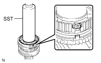
- SST
- 09308-14010
- HINT:
- Align the convex portion of the synchronizer ring with the groove of the clutch hub.
Install the clutch hub and confirm that the gear and synchronizer ring move smoothly.
| 7. INSTALL NO. 2 CLUTCH HUB SETTING SHAFT SNAP RING |
Select a snap ring that will allow minimum axial play.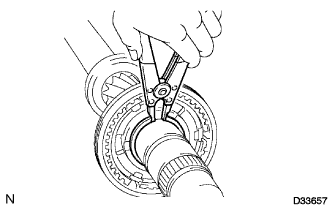
- Standard clearance:
- 0.1 mm (0.004 in.) or less
- Snap ring thickness:
Part No.
Thickness: mm (in.)
Mark
90520-42012
1.80 to 1.85
(0.0709 to 0.0728)
A
90520-42013
1.85 to 1.90
(0.0728 to 0.0748)
B
90520-42014
1.90 to 1.95
(0.0748 to 0.0768)
C
90520-42015
1.95 to 2.00
(0.0768 to 0.0787)
D
90520-42016
2.00 to 2.05
(0.0787 to 0.0807)
E
90520-42017
2.05 to 2.10
(0.0807 to 0.0827)
F
90520-42018
2.10 to 2.15
(0.0827 to 0.0846)
G
Using a snap ring expander, install the snap ring onto the input shaft.
| 8. INSTALL NO. 2 SYNCHRONIZER RING SET |
Coat the No. 2 synchronizer ring set with gear oil, then install it onto the input shaft.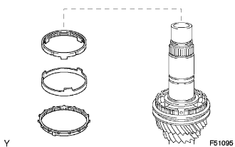
| 9. INSTALL SPACER |
Coat the spacer with gear oil, and install it onto the input shaft.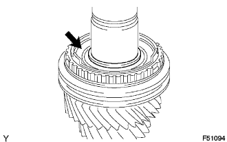
| 10. INSTALL 3RD GEAR NEEDLE ROLLER BEARING |
Coat the 3rd gear needle roller bearing with gear oil, and install it onto the input shaft.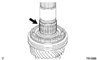
| 11. INSTALL STRAIGHT PIN |
Install the straight pin onto the input shaft.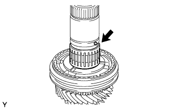
| 12. INSTALL 3RD GEAR |
Coat the 3rd gear with gear oil, and install it onto the input shaft.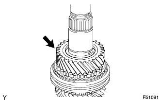
| 13. INSTALL 3RD GEAR THRUST WASHER |
Coat the 3rd gear thrust washer with gear oil, and install it onto the input shaft.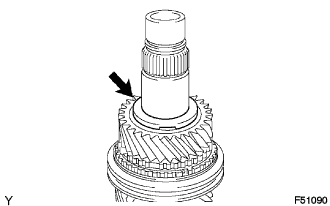
- HINT:
- Align the straight pin with the groove of the gear thrust washer and install it.
| 14. INSTALL GEAR THRUST WASHER SHAFT SNAP RING |
Select a snap ring that will allow minimum axial play.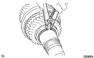
- Standard clearance:
- 0.1 mm (0.004 in.) or less
- Snap ring thickness:
Part No.
Thickness: mm (in.)
Mark
90520-39026
2.07 to 2.12
(0.0815 to 0.0835)
A
90520-39027
2.12 to 2.17
(0.0835 to 0.0854)
B
90520-39028
2.17 to 2.22
(0.0854 to 0.0874)
C
90520-39029
2.22 to 2.27
(0.0874 to 0.0894)
D
90520-39030
2.27 to 2.32
(0.0894 to 0.0913)
E
90520-39031
2.32 to 2.37
(0.0913 to 0.0933)
F
Using a snap ring expander, install the snap ring onto the input shaft.
| 15. INSTALL SPACER |
Coat the spacer with gear oil, and install it onto the input shaft.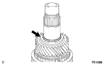
| 16. INSTALL 6TH GEAR NEEDLE ROLLER BEARING |
Coat the 6th gear needle roller bearing with gear oil, and install it onto the input shaft.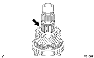
| 17. INSTALL 6TH GEAR |
Install the 6th gear onto the input shaft.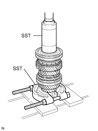
Install the synchronizer ring onto the input shaft.
Using SST and a press, install the clutch hub onto the input shaft.
- SST
- 09309-37010
09950-00020
Install the clutch hub and confirm that the gear and synchronizer ring move smoothly.
| 18. INSTALL TRANSMISSION CLUTCH HUB NO. 3 SHAFT SNAP RING |
Select a snap ring that will allow minimum axial play.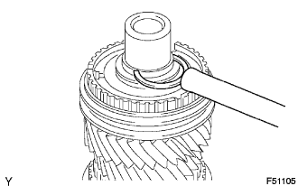
- Standard clearance:
- 0.1 mm (0.004 in.) or less
- Snap ring thickness:
Part No.
Thickness: mm (in.)
Mark
90520-33022
2.10 to 2.15
(0.0827 to 0.0847)
A
90520-33023
2.15 to 2.20
(0.0847 to 0.0866)
B
90520-33024
2.20 to 2.25
(0.0866 to 0.0886)
C
90520-33025
2.25 to 2.30
(0.0886 to 0.0906)
D
90520-33026
2.30 to 2.35
(0.0906 to 0.0925)
E
90520-33027
2.35 to 2.40
(0.0925 to 0.0945)
F
90520-33028
2.40 to 2.45
(0.0945 to 0.0965)
G
Using a brass bar and a hammer, install the snap ring onto the input shaft.
| 19. INSPECT 6TH GEAR THRUST CLEARANCE |
Using a dial indicator, measure the 6th gear thrust clearance.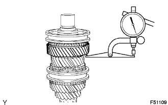
- Standard clearance:
- 0.20 to 0.48 mm (0.0079 to 0.0189 in.)
| 20. INSPECT 3RD GEAR THRUST CLEARANCE |
Using a feeler gauge, measure the 3rd gear thrust clearance.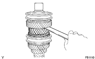
- Standard clearance:
- 0.19 to 0.51 mm (0.0075 to 0.0201 in.)
| 21. INSPECT 4TH GEAR THRUST CLEARANCE |
Using a dial indicator, measure the 4th gear thrust clearance.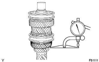
- Standard clearance:
- 0.12 to 0.38 mm (0.0047 to 0.0150 in.)
| 22. INSPECT 6TH GEAR RADIAL CLEARANCE |
Using a dial indicator, measure the 6th gear radial clearance.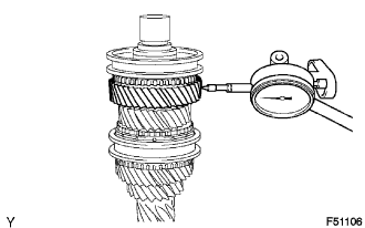
- Standard clearance:
- 0.015 to 0.065 mm (0.0006 to 0.0026 in.)
| 23. INSPECT 3RD GEAR RADIAL CLEARANCE |
Using a dial indicator, measure the 3rd gear radial clearance.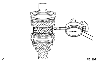
- Standard clearance:
- 0.015 to 0.067 mm (0.0006 to 0.0026 in.)
| 24. INSPECT 4TH GEAR RADIAL CLEARANCE |
Using a dial indicator, measure the 4th gear radial clearance.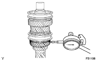
- Standard clearance:
- 0.015 to 0.067 mm (0.0006 to 0.0026 in.)