Front Passenger Side Seat Memory Switch Circuit
Circuit diagnosis
DESCRIPTION
The front passenger side seat memory switch sends signals to the front passenger side outer mirror control ECU via the multiplex communication system to memorize a given seat position. This memory system does not use a position sensor. The seat position is detected by counting pulses that are output when the motor turns. If there is no pulse output from the motor, the motor will stop operating. The front passenger side seat memory switch is later used to send signals to the front passenger side front power seat switch (position control ECU) to return the seat to one of the memorized positions.- A/T:
The front passenger side power seat memory operation can be performed only when the engine switch is on (IG) and the shift lever is in the P position.
- M/T:
The front passenger side power seat memory switch operation can be performed only when the engine switch is on (IG), apply the parking brake, and seat the vehicle speed below 3 km/h (1.9 mph).
WIRING DIAGRAM
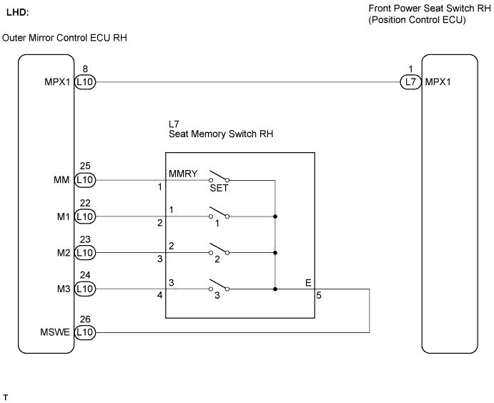

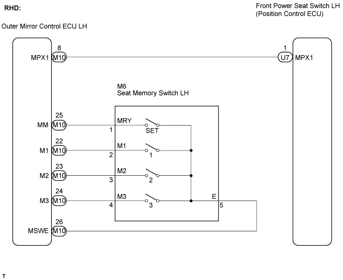
INSPECTION PROCEDURE
| 1. READ VALUE OF INTELLIGENT TESTER (SEAT MEMORY SWITCH) |

Connect the intelligent tester to the DLC3.
Turn the engine switch on (IG).
Read the DATA LIST.
SEAT: Item
Measurement Item/Range (Display)
Normal Condition
Diagnostic Note
Seat Memory No. 1
M1 switch signal / ON or OFF
ON: M1 switch is ON
OFF: M1 switch is OFF
-
Seat Memory No. 2
M2 switch signal / ON or OFF
ON: M2 switch is ON
OFF: M2 switch is OFF
-
Seat Memory No. 3
M3 switch signal / ON or OFF
ON: M3 switch is ON
OFF: M3 switch is OFF
-
Seat SET Switch
SET switch signal / ON or OFF
ON: SET switch is ON
OFF: SET switch is OFF
-
- OK:
- On the tester screen, each item changes between ON and OFF according to the above chart.
|
|
||||

| OK | ||
 |
||
| ||
| 2. INSPECT SEAT MEMORY SWITCH |
Remove the seat memory switch.
LHD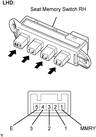
Measure the resistance according to the value(s) in the table below.
- Standard resistance:
Tester Connection
Switch Position
Specified Condition
1 (MMRY) - 5 (E)
SET switch is pressed
Below 1 Ω
2 (1) - 5 (E)
M1 switch is pressed
Below 1 Ω
3 (2) - 5 (E)
M2 switch is pressed
Below 1 Ω
4 (3) - 5 (E)
M3 switch is pressed
Below 1 Ω
1 (MMRY) - 5 (E)
SET switch is not pressed
10 kΩ or higher
2 (1) - 5 (E)
M1 switch is not pressed
10 kΩ or higher
3 (2) - 5 (E)
M2 switch is not pressed
10 kΩ or higher
4 (3) - 5 (E)
SET switch is not pressed
10 kΩ or higher
RHD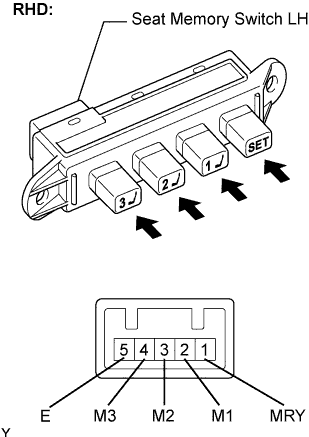
Measure the resistance according to the value(s) in the table below.
- Standard resistance:
Tester Connection
Switch Position
Specified Condition
1 (MRY) - 5 (E)
SET switch is pressed
Below 1 Ω
2 (M1) - 5 (E)
M1 switch is pressed
Below 1 Ω
3 (M2) - 5 (E)
M2 switch is pressed
Below 1 Ω
4 (M3) - 5 (E)
M3 switch is pressed
Below 1 Ω
1 (MRY) - 5 (E)
SET switch is not pressed
10 kΩ or higher
2 (M1) - 5 (E)
M1 switch is not pressed
10 kΩ or higher
3 (M2) - 5 (E)
M2 switch is not pressed
10 kΩ or higher
4 (M3) - 5 (E)
M3 switch is not pressed
10 kΩ or higher
|
|
||||

| OK | |
 |
| 3. CHECK HARNESS AND CONNECTOR (SEAT MEMORY SWITCH RH CIRCUIT) |
LHD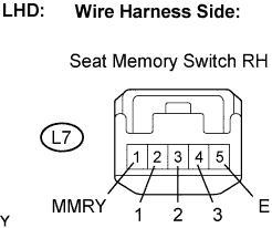
Measure the resistance according to the value(s) in the table below.
- Standard resistance:
Tester Connection
Specified Condition
L7-2 (1) - L7-5 (E)
10 kΩ or higher
L7-3 (2) - L7-5 (E)
10 kΩ or higher
L7-4 (3) - L7-5 (E)
10 kΩ or higher
L7-1 (MMRY) - L7-5 (E)
10 kΩ or higher
L7-5 (E) - Body ground
Below 1 Ω
RHD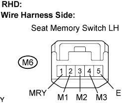
Measure the resistance according to the value(s) in the table below.
- Standard resistance:
Tester Connection
Specified Condition
M6-2 (M1) - M6-5 (E))
10 kΩ or higher
M6-3 (M2) - M6-5 (E)
10 kΩ or higher
M6-4 (M3) - M6-5 (E)
10 kΩ or higher
M6-1 (MRY) - M6-5 (E)
10 kΩ or higher
M6-5 (E) - Body ground
Below 1 Ω
|
|
||||
| OK | ||
|
||
| ||
| 4. CHECK HARNESS AND CONNECTOR (OUTER MIRROR CONTROL ECU - SEAT MEMORY SWITCH, BODY GROUND) |
LHD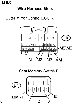
Disconnect the outer mirror control ECU RH connector.
Measure the resistance according to the value(s) in the table below.
- Standard resistance:
Tester Connection
Specified Condition
L10-22 (M1) - L7-2 (1)
Below 1 Ω
L10-23 (M2) - L7-3 (2)
Below 1 Ω
L10-24 (M3) - L7-4 (3)
Below 1 Ω
L10-25 (MM) - L7-1 (MMRY)
Below 1 Ω
L10-26 (MSWE) - L7-5 (E)
Below 1 Ω
L10-26 (MSWE) - Body ground
Below 1 Ω
L7-5 (E) - Body ground
Below 1 Ω
RHD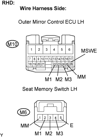
Disconnect the outer mirror control ECU LH connector.
Measure the resistance according to the value(s) in the table below.
- Standard resistance:
Tester Connection
Specified Condition
M10-22 (M1) - M6-2 (M1)
Below 1 Ω
M10-23 (M2) - M6-3 (M2)
Below 1 Ω
M10-24 (M3) - M6-4 (M3)
Below 1 Ω
M10-25 (MM) - M6-1 (MM)
Below 1 Ω
M10-26 (MSWE) - M6-5 (E)
Below 1 Ω
M10-26 (MSWE) - Body ground
Below 1 Ω
M6-5 (E) - Body ground
Below 1 Ω
|
|
||||
| OK | ||
|
||
| ||