Front Passenger Side ECU Power Source Circuit
Circuit diagnosis
DESCRIPTION
The front passenger side position control ECU is contained in the front passenger side front power seat switch.During manual operation, only one switch signal is accepted. If signals are input from 2 or more switches simultaneously, all of them are ignored, except when signals are input from the front vertical switch and lifter switch simultaneously. In this case, the signal from the lifter switch will operate.
During automatic operation, a manual switch input will override any other operations, i.e. automatic operations will stop and the manual input operation only will be accepted. For example, if a manual switch input is activated during a seat store/restore operation, the previous operation will cease and manual operation will be performed. After the manual operation is performed, the previous automatic operation will not resume.
The power mirror store/restore operation is unaffected by manual switch inputs.
The front passenger side front power seat switch does not allow the restore operation of the power seat when the system detects that the voltage of terminal SYSB is less than 8.0 +- 0.5 V for 30 msec. or is more than 10 +- 0.5 V for 30 msec.
This circuit is the power source circuit for the front passenger side front power seat switch (position control ECU).
- HINT:
- Manual adjustment of the slide, reclining, or lumbar can be performed even when the front passenger side front power seat switch is not functional if current is allowed to flow into terminals +B and SYSB.
- Manual adjustment of the slide, reclining, or lumbar can be performed even when the front passenger side front power seat switch is not functional if current is allowed to flow into terminals +B and SYSB.
WIRING DIAGRAM
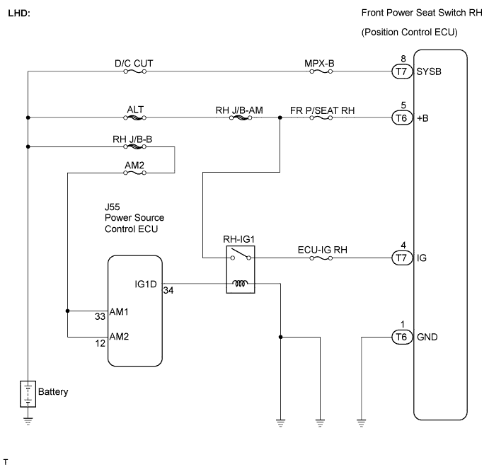

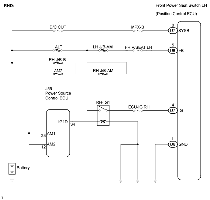
INSPECTION PROCEDURE
| 1. INSPECT FRONT POWER SEAT SWITCH (POSITION CONTROL ECU POWER SOURCE CIRCUIT) |

LHD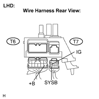
Disconnect the front power seat switch RH (position control ECU) connectors.
Measure the voltage according to the value(s) in the table below.
- Standard voltage:
Tester Connection
Condition
Specified Condition
T6-5 (+B) - Body ground
Always
10 to 14 V
T7-4 (IG) - Body ground
Engine switch on (IG)
10 to 14 V
T7-8 (SYSB) - Body ground
Always
10 to 14 V
RHD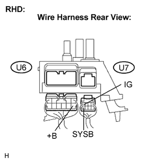
Disconnect the front power seat switch LH (position control ECU) connectors.
Measure the voltage according to the value(s) in the table below.
- Standard voltage:
Tester Connection
Condition
Specified Condition
U6-5 (+B) - Body ground
Always
10 to 14 V
U7-4 (IG) - Body ground
Engine switch on (IG)
10 to 14 V
U7-8 (SYSB) - Body ground
Always
10 to 14 V
|
|
||||

| OK | |
 |
| 2. INSPECT FRONT POWER SEAT SWITCH (POSITION CONTROL ECU GROUND CIRCUIT) |
LHD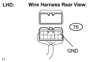
Measure the resistance according to the value(s) in the table below.
- Standard resistance:
Tester Connection
Condition
Specified Condition
T6-1 (GND) - Body ground
Always
Below 1 Ω
RHD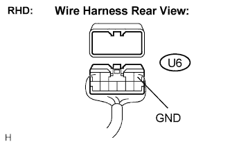
Measure the resistance according to the value(s) in the table below.
- Standard resistance:
Tester Connection
Condition
Specified Condition
U6-1 (GND) - Body ground
Always
Below 1 Ω
|
|
||||
| OK | ||
 |
||
| ||