Luggage Compartment Door Opener Circuit
Circuit diagnosis
DESCRIPTION
When the main body ECU RH has received the OFF signal from the luggage compartment opener main switch , the main body ECU RH activates the luggage compartment door lock motor when the ON signal from the luggage compartment door opener inner switch is received.WIRING DIAGRAM
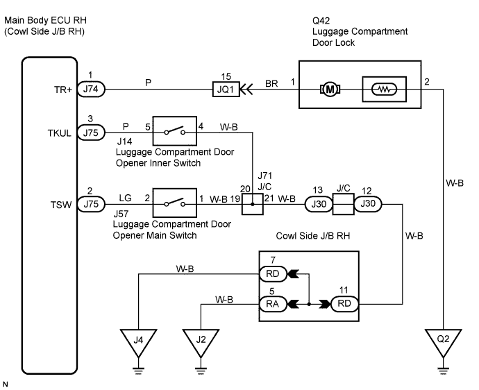

INSPECTION PROCEDURE
| 1. CHECK DTC OUTPUT (MULTIPLEX COMMUNICATION SYSTEM) |

Delete the DTC.
Check for DTC.
- OK:
- DTC B1200 is not output.
|
|
||||

| OK | |
 |
| 2. PERFORM ACTIVE TEST BY LUGGAGE COMPARTMENT DOOR LOCK ASSEMBLY |
Select the Active Test, use the intelligent tester to generate a control command, and check that the luggage compartment door lock motor operates.
| Item |
Test Details |
Diagnostic Note |
| Trunk/Bdor Open |
Operate luggage compartment door lock motor ON/OFF |
- |
- OK:
- Luggage compartment door lock motor operates.
|
|
||||

| NG | |
|
| 3. INSPECT LUGGAGE COMPARTMENT DOOR LOCK ASSEMBLY |
Remove the luggage compartment door lock assembly.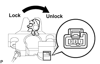
Move the door lock to the lock position.
Apply battery voltage to the door lock motor and check operation of the door lock motor.
OK: Measurement Condition
Specified Condition
Battery positive (+) → Terminal 1
Battery positive (-) → Terminal 2
Luggage compartment door lock motor unlock
|
|
||||
| OK | |
|
| 4. CHECK HARNESS AND CONNECTOR (LUGGAGE COMPARTMENT DOOR LOCK - MAIN BODY ECU RH) |
Disconnect the Q42 lock and J74 ECU connectors.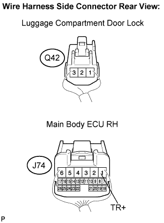
Measure the resistance according to the value(s) in the table below.
- Standard resistance:
Tester Connection
Condition
Specified Condition
Q42-1 - J74-1 (TR+)
Always
Below 1 Ω
Q42-1 - Body ground
Always
10 kΩ or higher
Q42-2 - Body ground
Always
Below 1 Ω
|
|
||||
| OK | |
|
| 5. READ VALUE OF INTELLIGENT TESTER |
Connect the intelligent tester to the DLC3.
Turn the engine switch on (IG) and the turn the intelligent tester main switch on.
Select Trunk/B Door Open SW and Trunk Main SW in the Data List and read the value displayed on the intelligent tester.
Item
Measurement Item/Display (Range)
Normal Condition
Diagnostic Note
Trunk/B Door Open SW
Luggage compartment door opener inner switch/ON or OFF
ON: Luggage compartment door opener inner switch is pressed
OFF: Luggage compartment door opener inner switch is not pressed
-
Trunk Main SW
Luggage compartment door opener main switch signal/ON or OFF
ON: Luggage compartment door opener main switch is pushed
ON: Luggage compartment door opener main switch is not pushed
-
- OK:
- ON (luggage compartment door opener inner switch is pressed) appears on the tester.
- OK:
- ON (luggage compartment door opener main switch is pressed) appears on the tester.
Result Result
Proceed to
NG (Luggage compartment door opener main switch)
A
NG (Luggage compartment door opener inner switch)
B
OK (Luggage compartment door opener main switch and luggage compartment door opener inner switch)
C
|
|
||||
|
|
||||
| A | |
|
| 6. INSPECT LUGGAGE COMPARTMENT DOOR OPENER MAIN SWITCH |
Remove the luggage compartment door opener main switch.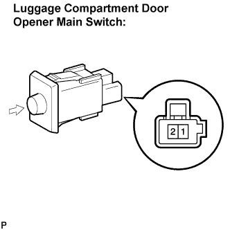
Measure the resistance according to the value(s) in the table below.
- Standard resistance:
Tester Connection
Condition
Specified Condition
1 - 2
Switch free (OFF)
10 kΩ or higher
Switch pushed (ON)
Below 1 Ω
|
|
||||
| OK | |
|
| 7. CHECK HARNESS AND CONNECTOR (LUGGAGE COMPARTMENT DOOR OPENER MAIN SW - MAIN BODY ECU RH) |
Install the luggage compartment door opener main switch.
Disconnect the J57 switch and J75 ECU connectors.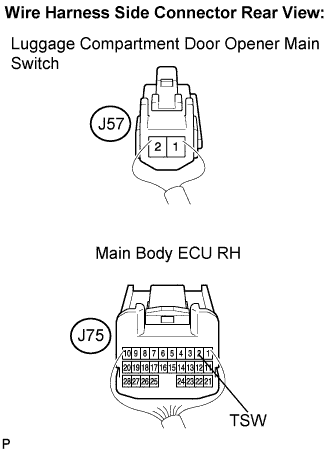
Measure the resistance according to the value(s) in the table below.
- Standard resistance:
Tester Connection
Condition
Specified Condition
J57-2 - J75-2 (TSW)
Always
Below 1 Ω
J57-2 - Body ground
Always
10 kΩ or higher
J57-1 - Body ground
Always
Below 1 Ω
|
|
||||
| OK | ||
 |
||
| ||
| 8. INSPECT LUGGAGE COMPARTMENT DOOR OPENER INNER SWITCH |
Remove the luggage compartment door opener inner switch.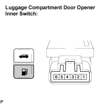
Measure the resistance according to the value(s) in the table below.
- Standard resistance:
Tester Connection
Condition
Specified Condition
4 - 5
Switch free (OFF)
10 kΩ or higher
Switch pushed (ON)
Below 1 Ω
|
|
||||
| OK | |
|
| 9. CHECK HARNESS AND CONNECTOR (LUGGAGE COMPARTMENT DOOR OPENER INNER SW - MAIN BODY ECU RH) |
Install the luggage compartment door opener switch.
Disconnect the J14 switch and J75 ECU connectors.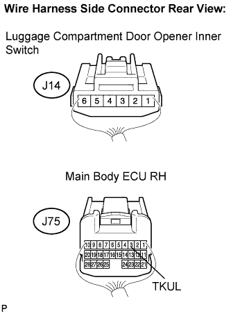
Measure the resistance according to the value(s) in the table below.
- Standard resistance:
Tester Connection
Condition
Specified Condition
J14-5 - J75-3 (TKUL)
Always
Below 1 Ω
J14-5 - Body ground
Always
10 kΩ or higher
J14-4 - Body ground
Always
Below 1 Ω
|
|
||||
| OK | ||
|
||
| ||