C1523
Diagnostic trouble codes
DESCRIPTION
The power steering ECU assembly supplies current to the power steering motor through this circuit.| DTC No. |
DTC Detection Item |
Trouble Area |
| C1523 |
Excessively large current deviation |
|
| C1524 |
Voltage error between motor terminals |
|
WIRING DIAGRAM
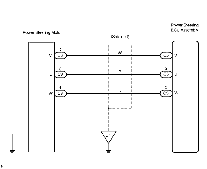

INSPECTION PROCEDURE
| 1. CHECK HARNESS AND CONNECTOR (POWER STEERING ECU ASSEMBLY - POWER STEERING MOTOR) |

Disconnect the C5 connector from the power steering ECU assembly.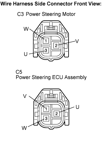
Disconnect the C3 connector from the power steering motor.
Measure the resistance according to the value(s) in the table below.
- Standard resistance:
Tester Connection
Condition
Specified Condition
C5-1 (V) - C3-2 (V)
Always
Below 1 Ω
C5-2 (U) - C3-3 (U)
Always
Below 1 Ω
C5-3 (W) - C3-1 (W)
Always
Below 1 Ω
C5-1 (V) - Body ground
Always
10 kΩ or higher
C5-2 (U) - Body ground
Always
10 kΩ or higher
C5-3 (W) - Body ground
Always
10 kΩ or higher
|
|
||||

| OK | |
 |
| 2. INSPECT POWER STEERING GEAR ASSEMBLY (POWER STEERING MOTOR) |
Measure the resistance according to the value(s) in the table below.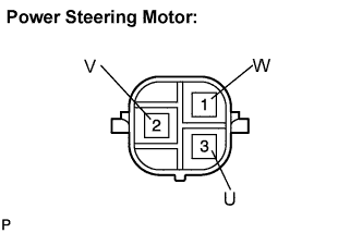
- Standard resistance:
Tester Connection
Condition
Specified Condition
C3-3 (U) - C3-2 (V)
Always
Below 1 Ω
C3-2 (V) - C3-1 (W)
Always
Below 1 Ω
C3-1 (W) - C3-3 (U)
Always
Below 1 Ω
C3-3 (U) - Body ground
Always
10 kΩ or higher
C3-2 (V) - Body ground
Always
10 kΩ or higher
C3-1 (W) - Body ground
Always
10 kΩ or higher
- NOTICE:
- If replacing the power steering gear assembly, clear the rotation angle sensor value calibration value, initialize the rotation angle sensor, and calibrate the torque sensor zero point (Click here).
- If replacing the power steering gear assembly, clear the rotation angle sensor value calibration value, initialize the rotation angle sensor, and calibrate the torque sensor zero point (Click here).
- NOTICE:
- If replacing the power steering ECU assembly, initialize the rotation angle sensor value and calibrate the torque sensor zero point (Click here).
|
|
||||
| OK | ||
 |
||
| ||