Seat Illumination Circuit
Circuit diagnosis
DESCRIPTION
The seat illumination can be canceled using the overhead J/B switch.The turning on and off of the seat illumination is controlled by the main body ECU LH based on various signals received through BEAN communication.
The main body ECU LH includes a MOS-FET (Metal Oxide Semiconductor - Field Effect Transistor) circuit that fades the seat illumination in and out by duty control.
This MOS-FET circuit has an overheat protection function as a fail-safe. If the main body ECU LH becomes excessively hot, the seat illumination turns off and remains off.
Normal operation will resume when the conditions required to turn on the seat illumination are met again.
WIRING DIAGRAM
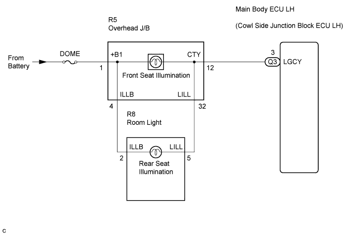

INSPECTION PROCEDURE
| 1. CHECK PERSONAL LIGHT (OPERATION) |

- HINT:
- The personal lights and seat illumination share the same power source circuit. Therefore, if none of them come on, inspect the power source circuit first.
Push the personal light switches.
Check that personal lights come on.
- OK:
- Personal lights come on.
|
|
||||

| OK | |
 |
| 2. PERFORM ACTIVE TEST BY INTELLIGENT TESTER |
Connect the intelligent tester to the DLC3.
Turn the engine switch on (IG).
Turn the intelligent tester main switch on.
Select the item(s) in the ACTIVE TEST, and check the operation.
ACTIVE TEST: Body No. 3 (Main body ECU LH) Item
Test Details
Diagnostic Note
Interior Light (Dim) Operation
Front and rear seat illumination ON / OFF
-
- OK:
- Front and rear seat illumination come on.
- Result:
Result
Proceed to
Front seat illumination does not come on
A
Rear seat illumination does not come on
B
Neither front nor rear seat illumination comes on
C
OK
D
- HINT:
- If the rear seat illumination comes on normally, but the front seat illumination does not come on, there is an open circuit in the overhead J/B.
|
|
||||
|
|
||||
|
|
||||

| D | ||
 |
||
| ||
| 3. INSPECT REAR DOME LIGHT ASSEMBLY (REAR SEAT ILLUMINATION) |
Remove the rear dome light assembly.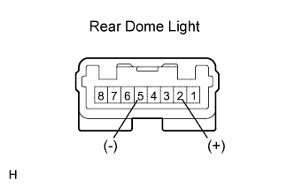
Connect the (+) lead from the battery to terminal 2 and the (-) lead to terminal 5, and then check that the seat illumination comes on.
- OK:
- Seat illumination comes on.
|
|
||||
| OK | |
|
| 4. CHECK HARNESS AND CONNECTOR (OVERHEAD J/B - REAR DOME LIGHT ASSEMBLY) |
Disconnect the R8 rear dome light assembly connector.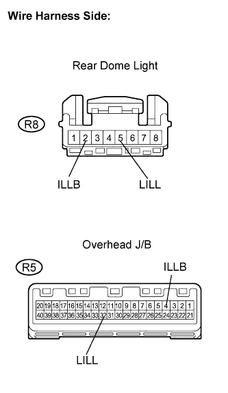
Disconnect the R5 overhead J/B connector.
Measure the resistance according to the value(s) in the table below.
- Standard resistance:
Tester Connection
Condition
Specified Condition
R8-2 (ILLB) - R5-4 (ILLB)
Always
Below 1 Ω
R8-5 (LILL)- R5-32 (LILL)
Always
Below 1 Ω
R8-2 (ILLB) - Body ground
Always
10 kΩ or higher
R8-5 (LILL) - Body ground
Always
10 kΩ or higher
|
|
||||
| OK | ||
|
||
| ||
| 5. CHECK HARNESS AND CONNECTOR (MAIN BODY ECU LH - OVERHEAD J/B) |
Disconnect the Q1 main body ECU LH connector.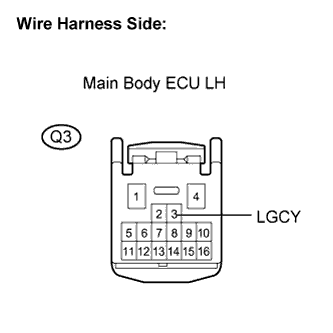
Measure the voltage according to the value(s) in the table below.
- Standard voltage:
Tester Connection
Condition
Specified Condition
Q3-3 (LGCY) - Body ground
Always
10 to 14 V
|
|
||||
| OK | ||
|
||
| ||
| 6. CHECK HARNESS AND CONNECTOR (MAIN BODY ECU LH - OVERHEAD J/B) |
Disconnect the Q1 main body ECU LH connector.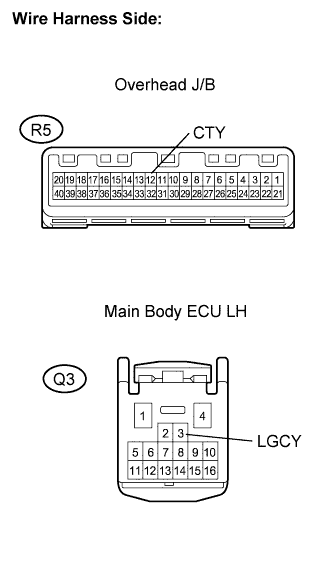
Disconnect the R5 overhead J/B connector.
Measure the resistance according to the value(s) in the table below.
- Standard resistance:
Tester Connection
Condition
Specified Condition
Q3-3 (LGCY) - R5-12 (CTY)
Always
Below 1 Ω
Q3-3 (LGCY) - Body ground
Always
10 kΩ or higher
|
|
||||
| OK | ||
|
||
| ||
| 7. CHECK HARNESS AND CONNECTOR (POWER SOURCE) |
Disconnect the R5 overhead J/B connector.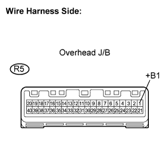
Measure the voltage according to the value(s) in the table below.
- Standard voltage:
Tester Connection
Condition
Specified Condition
R5-1 (+B1) - Body ground
Always
10 to 14 V
|
|
||||
| OK | ||
|
||
| ||