ON-VEHICLE INSPECTION
Inspection
| INSPECT AUTOMATIC LIGHT CONTROL SENSOR |

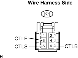  |
Disconnect the K1 sensor connector.
Connect the voltmeter's positive (+) lead to terminal 6 and the negative (-) lead to terminal 3.
Measure the voltage of the connector.
- Standard voltage:
Tester Connection
Condition
Specified Condition
K1-3 (CTLE) - K1-6 (CTLB)
Engine switch on (IG)
10 to 14 V
Measure the resistance of the connector.
- Standard resistance:
Tester Connection
Condition
Specified Condition
K1-3 (CTLE) - Body ground
Always
Below 1 Ω
Reconnect the K1 sensor connector.
Check the waveform of the K1 sensor connector.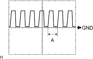
Tester Connection
Condition
Specified Condition
Tester Range
K1-3 (CTLE) - K1-5 (CTLS)
Engine switch on (IG), Headlight dimmer switch in AUTO
Correct waveform is as shown
5 V/DIV., 5 msec./DIV.
- HINT:
- If the ambient light becomes brighter, width A becomes narrower.