PS Warning Light Remains ON
Circuit diagnosis
DESCRIPTION
The power steering ECU is connected to the combination meter via CAN and multiplex communications. If any of the following are detected, the PS warning light remains on.- The power steering ECU connectors are disconnected from the power steering ECU.
- There is a malfunction in the power steering ECU internal circuit.
- There is an open in the harness between the combination meter and power steering ECU assembly.
WIRING DIAGRAM
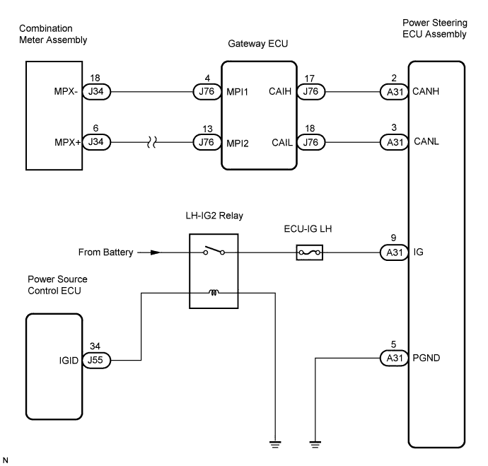

INSPECTION PROCEDURE
| 1. CHECK HARNESS AND CONNECTOR |

Check the indication condition of the PS warning light while wiggling the power steering ECU assembly connector and wire harness up and down, and right and left.
- OK:
- PS warning light indication condition does not change.
|
|
||||

| OK | |
 |
| 2. INSPECT CAN COMMUNICATION SYSTEM |
Using the intelligent tester, check for DTCs and confirm that there are no problems in the CAN communication system.
- OK:
- DTCs are not output.
|
|
||||
| OK | |
|
| 3. INSPECT MULTIPLEX COMMUNICATION SYSTEM |
Using the intelligent tester, check for DTCs and confirm that there are no problems in the multiplex communication system (BEAN).
- OK:
- DTCs are not output.
|
|
||||
| OK | |
|
| 4. INSPECT FUSE |
Remove the ECU-IG LH fuse from the cowl side J/B LH.
Check for continuity of the ECU-IG LH fuse.
- OK:
- Below 1 Ω
|
|
||||
| OK | |
|
| 5. INSPECT POWER STEERING ECU ASSEMBLY |
Disconnect the A31 connector from the power steering ECU assembly.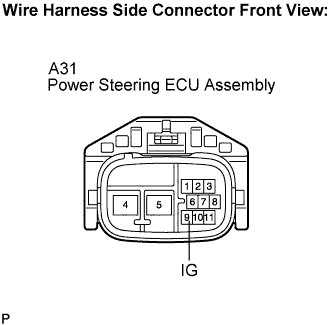
Measure the voltage according to the value(s) in the table below.
- Standard voltage:
Tester Connection
Condition
Specified Condition
A31-9 (IG) - Body ground
Engine switch on (IG)
10 to 14 V
|
|
||||
| OK | |
|
| 6. CHECK HARNESS AND CONNECTOR (POWER STEERING ECU ASSEMBLY - BODY GROUND) |
Measure the resistance according to the value(s) in the table below.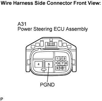
- Standard resistance:
Tester Connection
Condition
Specified Condition
A31-5 (PGND) - Body ground
Engine switch on (IG)
Below 1 Ω
|
|
||||
| OK | |
|
| 7. INSPECT COMBINATION METER ASSEMBLY |
Connect the intelligent tester to the DLC3.
Turn the engine switch on (IG).
Perform the Active Test according to the display on the tester.
Combination Meter: Item
Test Details
Diagnostic Note
Indicat EPS
PS indicator light OFF/ON
-
- OK:
- PS indicator light comes on.
- NOTICE:
- If replacing the power steering ECU assembly, initialize the rotation angle sensor value and calibrate the torque sensor zero point (Click here).
|
|
||||
| OK | ||
 |
||
| ||