REMOVAL
Removal / installation
| 1. REMOVE STEERING COLUMN COVER (for Manual Tilt and Telescopic) |

Remove the 2 screws.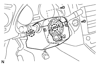

Disengage the 2 claws to remove the lower steering column cover.
Disengage the 4 clips to separate the steering column cover upper.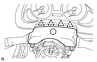
Disengage the claw to remove the upper steering column cover.
| 2. REMOVE STEERING COLUMN COVER (for Power Tilt and Power Telescopic) |
Remove the 3 screws.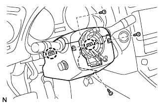
Disengage the 2 claws to remove the steering column cover lower.
- NOTICE:
- Do not damage the tilt and telescopic switch.
Disengage the 4 clips to separate the steering column cover upper.
Disengage the claw to remove the steering column cover upper.
| 3. REMOVE FRONT DOOR SCUFF PLATE LH (w/o Illumination) |
Put protective tape around the front door scuff plate.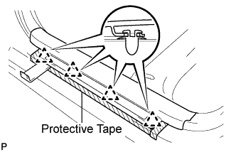
Using a moulding remover, disengage the 4 clips.
Disengage the 7 claws and remove the front door scuff plate LH.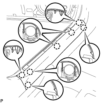
| 4. REMOVE FRONT DOOR SCUFF PLATE LH (w/ Illumination) |
Put protective tape around the front door scuff plate.
Using a moulding remover, disengage the 4 clips.
Disengage the 7 claws and remove the front door scuff plate LH.
Disconnect the connector.
| 5. REMOVE FRONT DOOR OPENING TRIM COVER LH |
Disengage the 6 claws and remove the front door opening trim cover LH.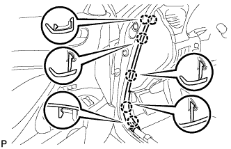
| 6. REMOVE SIDE INSTRUMENT PANEL LH |
Using a moulding remover, disengage the 5 claws and 3 clips, and then remove the side instrument panel LH.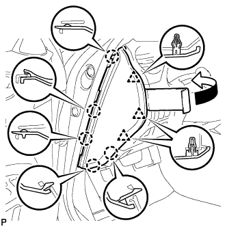
| 7. REMOVE LOWER INSTRUMENT PANEL FINISH PANEL SUB-ASSEMBLY |
Disengage the 7 clips.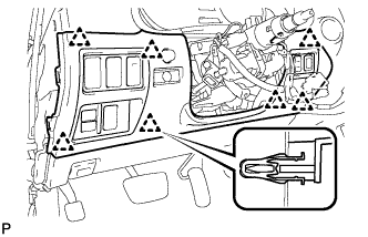
Disconnect the connectors and remove the lower instrument panel finish panel sub-assembly.
| 8. REMOVE INSTRUMENT CLUSTER FINISH PANEL SUB-ASSEMBLY |
Remove the 2 screws <G> and 2 clips, and then remove the instrument cluster finish panel sub-assembly.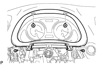
| 9. REMOVE WINDSHIELD WIPER SWITCH ASSEMBLY |
Disconnect the 2 connectors.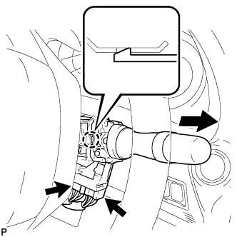
Disengage the claw and remove the windshield wiper switch assembly as shown in the illustration.
- NOTICE:
- If the claw is pushed with excessive force, it may break.
| 10. REMOVE COMBINATION METER ASSEMBLY |
Attach protective tape to the position indicated in the illustration.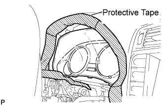
Using a screwdriver, disengage the claw.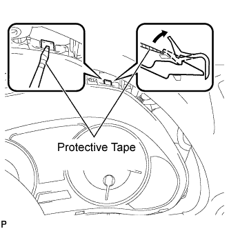
- HINT:
- Tape the screwdriver tip before use.
Using a screwdriver, disengage the claw, and pull out the combination meter assembly.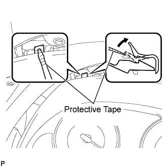
- HINT:
- Tape the screwdriver tip before use.
Disconnect the connectors and remove the combination meter assembly as shown in the illustration.
- NOTICE:
- Do not damage the instrument panel safety pad or combination meter assembly when removing the combination meter assembly.
| 11. REMOVE TURN SIGNAL FLASHER ASSEMBLY |
Disconnect the connector.
Disengage the clamp and remove the turn signal flasher assembly.