INSTALLATION
Removal / installation
| 1. INSTALL RADIO RECEIVER ASSEMBLY (w/o Navigation System) |

Install the radio receiver assembly as shown in the illustration.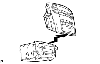

| 2. INSTALL NO. 2 RADIO BRACKET (w/o Navigation System) |
Install the radio No. 2 bracket with the 6 bolts.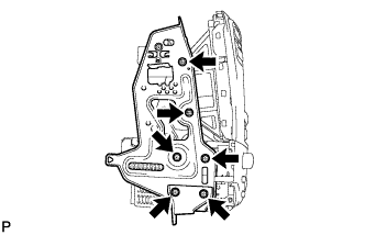
| 3. INSTALL NO. 1 RADIO BRACKET (w/o Navigation System) |
Install the radio No. 1 bracket with the 6 bolts.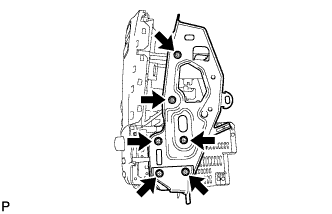
| 4. INSTALL INTEGRATION CONTROL PANEL WITH RADIO RECEIVER ASSEMBLY (w/o Navigation System) |
Connect each connector.
Install the integration control panel w/ radio receiver assembly with the 4 bolts.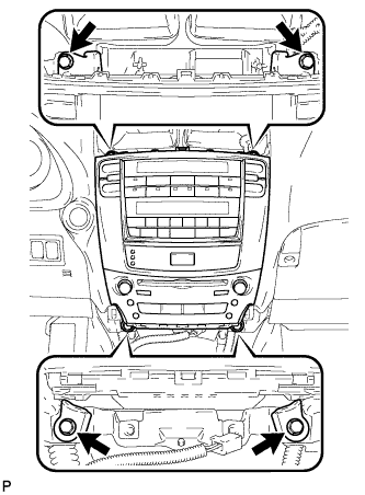
| 5. INSTALL RADIO RECEIVER ASSEMBLY (w/ Navigation System) |
Install the radio receiver assembly as shown in the illustration.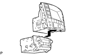
| 6. INSTALL NO. 2 RADIO BRACKET (w/ Navigation System) |
Install the radio No. 2 bracket with the 7 bolts.
| 7. INSTALL NO. 1 RADIO BRACKET (w/ Navigation System) |
Install the radio No. 1 bracket with the 7 bolts.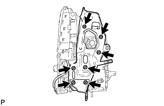
Engage the connector clamp.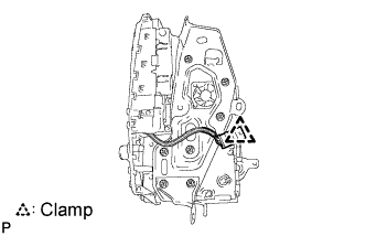
| 8. INSTALL MULTI-DISPLAY WITH RADIO RECEIVER ASSEMBLY (w/ Navigation System) |
Connect each connector.
Install the the multi-display w/ radio receiver assembly with the 4 bolts.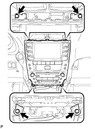
| 9. INSTALL CENTER LOWER INSTRUMENT CLUSTER FINISH PANEL |
Engage the 4 claws and install the center lower instrument cluster finish panel.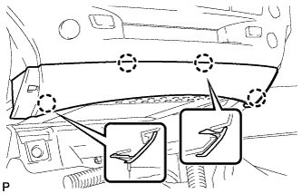
| 10. INSTALL NO. 3 INSTRUMENT PANEL REGISTER ASSEMBLY |
Connect the connectors.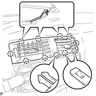
Engage the 11 claws and install the No. 3 instrument panel register assembly.
| 11. INSTALL CONSOLE BOX |
Engage the 2 claws and 2 clips.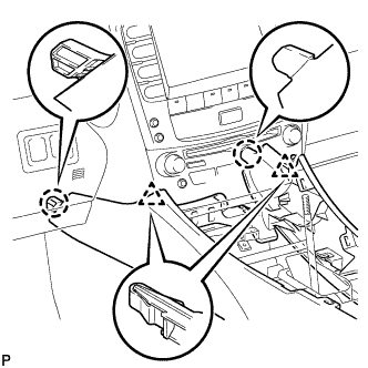
Install the 2 bolts <C>.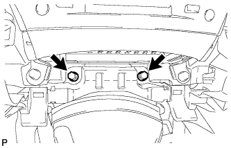
Install the 2 bolts <C>.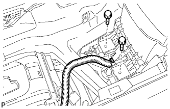
Connect the connector.
Connect the connectors.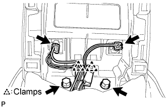
Engage the 2 clamps.
Install the 2 bolts <C>.
| 12. INSTALL CONSOLE BOX REGISTER ASSEMBLY |
Engage the 2 claws and 4 clips, and then install the console box register assembly.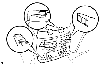
Install the rear ash receptacle assembly.
| 13. INSTALL FRONT ASH RECEPTACLE SUB-ASSEMBLY |
Connect the connectors.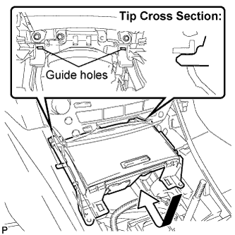
Insert the protruding parts of the front ash receptacle sub-assembly into the 2 guide holes as shown in the illustration.
Install the front ash receptacle sub-assembly with the 2 screws <F>.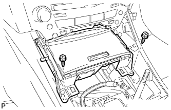
| 14. INSTALL FRONT CONSOLE PANEL SUB-ASSEMBLY (for Manual Transmission) |
Engage the 6 clips.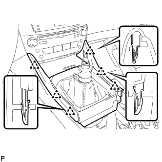
Close the snap.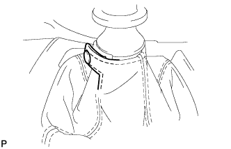
| 15. INSTALL REAR CONSOLE PANEL SUB-ASSEMBLY (for Manual Transmission) |
Engage the 7 claws and 2 clips.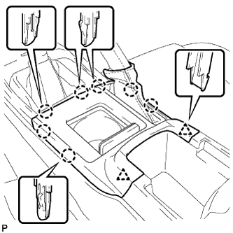
Close the snap.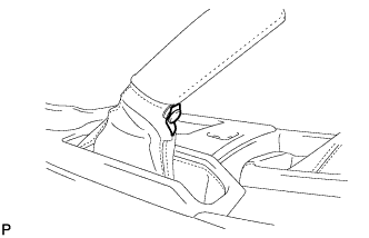
| 16. INSTALL CONSOLE PANEL SUB-ASSEMBLY (for Automatic Transmission) |
Connect the connectors.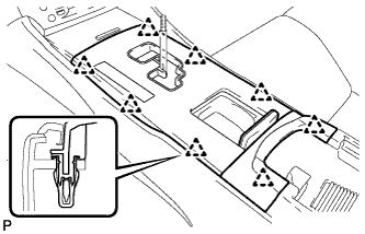
Engage the 8 clips and install the console panel sub-assembly.
| 17. INSTALL NO. 2 UPPER CONSOLE PANEL GARNISH (for Automatic Transmission) |
Engage the claw and 2 clips, and then install the upper No. 2 console panel garnish.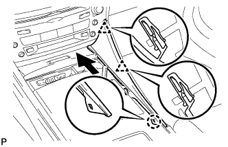
| 18. INSTALL NO. 1 UPPER CONSOLE PANEL GARNISH (for Automatic Transmission) |
Engage the claw and 2 clips, and then install the upper No. 1 console panel garnish.
| 19. INSTALL SHIFT LEVER KNOB SUB-ASSEMBLY (for Manual Transmission) |
| 20. INSTALL SHIFT LEVER KNOB SUB-ASSEMBLY (for Automatic Transmission) |