Satellite Switch Circuit
Circuit diagnosis
DESCRIPTION
- The meter CPU receives satellite switch signals from the satellite switch in this circuit.
- The meter CPU sends satellite switch signals to the AFS ECU, and clearance sonar ECU using the BEAN lines. Each ECU controls every system based on these signals.
WIRING DIAGRAM
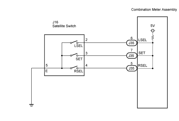

INSPECTION PROCEDURE
| 1. INSPECT SATELLITE SWITCH |

Disconnect the connector from the satellite switch.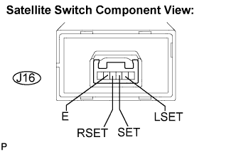
Measure the resistance according to the value(s) in the table below.
- Standard resistance:
Tester Connection
Condition
Specified Condition
J16-2 (LSET) - J16-5 (E)
Satellite switch LH is pressed
Below 1 Ω
J16-2 (LSET) - J16-5 (E)
Satellite switch LH is not pressed
10 kΩ or higher
J16-3 (SET) - J16-5 (E)
Satellite switch ON/OFF is pressed
Below 1 Ω
J16-3 (SET) - J16-5 (E)
Satellite switch ON/OFF is not pressed
10 kΩ or higher
J16-4 (RSET) - J16-5 (E)
Satellite switch RH is pressed
Below 1 Ω
J16-4 (RSET) - J16-5 (E)
Satellite switch RH is not pressed
Below 1 Ω
|
|
||||

| OK | |
 |
| 2. CHECK HARNESS AND CONNECTOR (COMBINATION METER - SATELLITE SWITCH) |
Disconnect the J35 and J16 connectors.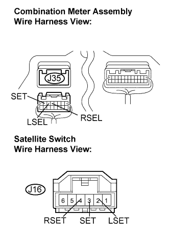
Measure the resistance according to the value(s) in the table below.
- Standard resistance:
Tester Connection
Condition
Specified Condition
J35-5 (RSEL) - J16-4 (RSET)
Always
Below 1 Ω
J35-6 (LSEL) - J16-2 (LSET)
Always
Below 1 Ω
J35-7 (SEL) - J16-3 (SET)
Always
Below 1 Ω
J16-2 (LSET) - Body ground
Always
10 kΩ or higher
J16-3 (SET) - Body ground
Always
10 kΩ or higher
J16-4 (RSET) - Body ground
Always
10 kΩ or higher
|
|
||||
| OK | ||
 |
||
| ||