74-40
Diagnostic trouble codes
DESCRIPTION
| DTC No. |
DTC Detection Condition |
Trouble Area |
| 74-40 |
A short is detected in the speaker output circuit. |
|
- When a short in the speaker circuit is detected, all sound output is stopped.
WIRING DIAGRAM
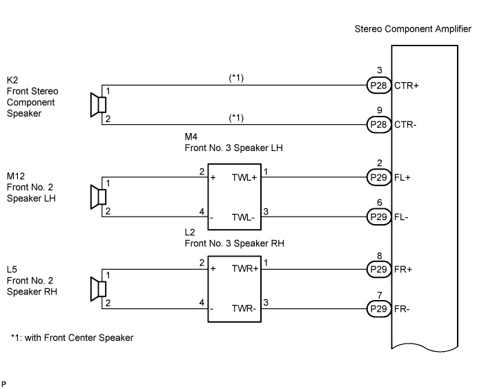

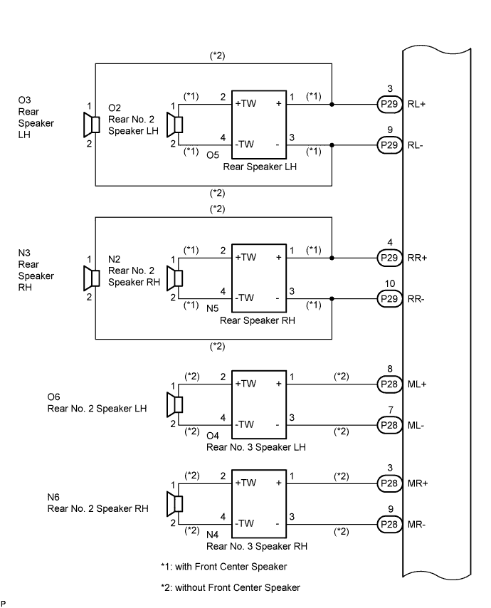
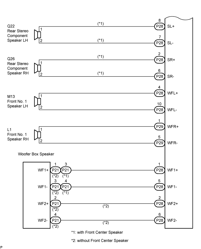
INSPECTION PROCEDURE
- HINT:
- After the inspection is completed, clear the DTCs.
| 1. INSPECT STEREO COMPONENT AMPLIFIER |

Disconnect the stereo amplifier connectors P29 and P28.
Clear the DTCs and recheck for DTCs.
Check if DTC 74-40 is output.
- OK:
- DTC 74-40 is not output.
|
|
||||

| OK | |
 |
| 2. CHECK OPERATION |
Reconnect the stereo component amplifier connector P29.
Check if DTC 74-40 is output.
- OK:
- DTC 74-40 is not output.
|
|
||||

| OK | |
|
| 3. CHECK HARNESS AND CONNECTOR |
Disconnect the connectors shown in the illustration from the stereo component amplifier and speakers.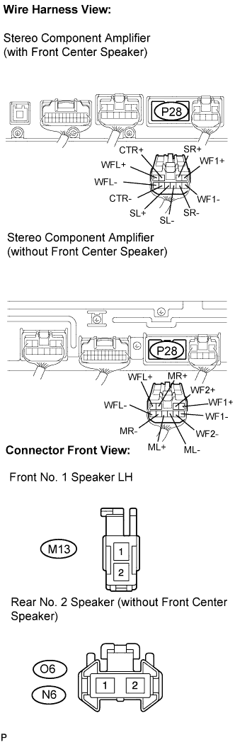
Measure the resistance according to the value(s) in the table below.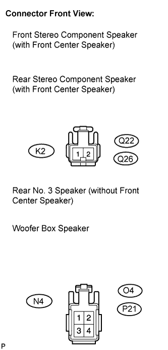
- Standard resistance:
Tester connection
Condition
Specified condition
CTR+ - Body ground (*1)
Always
10 kΩ or higher
CTR- - Body ground (*1)
Always
10 kΩ or higher
ML+ - Body ground (*2)
Always
10 kΩ or higher
ML- - Body ground (*2)
Always
10 kΩ or higher
O4-2 - Body ground (*2)
Always
10 kΩ or higher
O4-4 - Body ground (*2)
Always
10 kΩ or higher
MR+ - Body ground (*2)
Always
10 kΩ or higher
MR- - Body ground (*2)
Always
10 kΩ or higher
N4-2 - Body ground (*2)
Always
10 kΩ or higher
N4-4 - Body ground (*2)
Always
10 kΩ or higher
SL+ - Body ground (*1)
Always
10 kΩ or higher
SL- - Body ground (*1)
Always
10 kΩ or higher
SR+ - Body ground (*1)
Always
10 kΩ or higher
SR- - Body ground (*1)
Always
10 kΩ or higher
WFL+ - Body ground
Always
10 kΩ or higher
WFL- - Body ground
Always
10 kΩ or higher
WF2+ - Body ground (*2)
Always
10 kΩ or higher
WF2- - Body ground (*2)
Always
10 kΩ or higher
WF1+ - Body ground
Always
10 kΩ or higher
WF1- - Body ground
Always
10 kΩ or higher
|
|
||||
| OK | |
|
| 4. INSPECT FRONT NO. 1 SPEAKER (LEFT HAND) |
Resistance check.
Measure the resistance between the terminals of the speaker.
- Standard resistance:
- with Front Center Speaker:
- 6 to 10 Ω
- without Front Center Speaker:
- Approximately 4 Ω
|
|
||||
| OK | |
|
| 5. CONFIRM MODEL |
- Result:
Result
Proceed to
without Front Center Speaker
A
with Front Center Speaker
B
|
|
||||
| A | |
|
| 6. INSPECT REAR NO. 2 SPEAKER (RIGHT HAND) |
Reconnect the stereo component amplifier connector and rear No. 2 speaker connector.
Check that audio sound can be heard from the speaker.
- OK:
- Audio sound can be heard.
|
|
||||
| OK | |
|
| 7. INSPECT REAR NO. 2 SPEAKER (LEFT HAND) |
Reconnect the stereo component amplifier connector and rear No. 2 speaker connector.
Check that audio sound can be heard from the speaker.
- OK:
- Audio sound can be heard.
|
|
||||
| OK | |
|
| 8. INSPECT REAR NO. 3 SPEAKER (RIGHT HAND) |
Reconnect the stereo component amplifier connector and rear No. 3 speaker connector.
Check that audio sound can be heard from the speaker.
- OK:
- Audio sound can be heard.
|
|
||||
| OK | |
|
| 9. INSPECT REAR NO. 3 SPEAKER (LEFT HAND) |
Reconnect the stereo component amplifier connector and rear No. 3 speaker connector.
Check that audio sound can be heard from the speaker.
- OK:
- Audio sound can be heard.
|
|
||||
| NG | ||
 |
||
| ||
| 10. INSPECT REAR STEREO COMPONENT SPEAKER (LEFT HAND) |
Reconnect the stereo component amplifier connector and rear stereo component speaker connector.
Check that audio sound can be heard from the speaker.
- OK:
- Audio sound can be heard.
|
|
||||
| OK | |
|
| 11. INSPECT REAR STEREO COMPONENT SPEAKER (RIGHT HAND) |
Reconnect the stereo component amplifier connector and rear stereo component speaker connector.
Check that audio sound can be heard from the speaker.
- OK:
- Audio sound can be heard.
|
|
||||
| OK | |
|
| 12. INSPECT FRONT STEREO COMPONENT SPEAKER |
Resistance check.
Measure the resistance between the terminals of the speaker.
- Standard resistance:
- 7 to 9 Ω
|
|
||||
| OK | |
|
| 13. INSPECT WOOFER BOX SPEAKER |
Resistance check.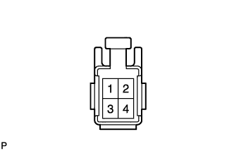
Measure the resistance according to the value(s) in the table below.
- NOTICE:
- The speaker should not be removed for checking.
- Standard resistance:
- with Front Center Speaker:
Tester connection
Condition
Specified condition
3 - 4
Always
7 to 8.6 Ω
- without Front Center Speaker:
Tester connection
Condition
Specified condition
1 - 3
Always
Approximately 2 Ω
2 - 4
Always
Approximately 2 Ω
|
|
||||
| OK | |
|
| 14. CHECK HARNESS AND CONNECTOR |
Disconnect the connectors shown in the illustration from the stereo component amplifier and speakers.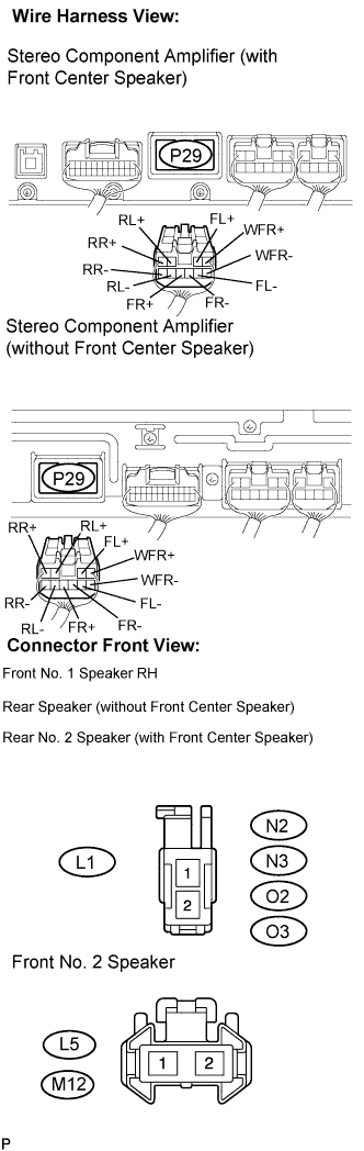
Measure the resistance according to the value(s) in the table below.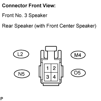
- Standard resistance:
Tester connection
Condition
Specified condition
FL+ - Body ground
Always
10 kΩ or higher
FL- - Body ground
Always
10 kΩ or higher
M4-2 - Body ground
Always
10 kΩ or higher
M4-4 - Body ground
Always
10 kΩ or higher
FR+ - Body ground
Always
10 kΩ or higher
FR- - Body ground
Always
10 kΩ or higher
L2-2 - Body ground
Always
10 kΩ or higher
L2-4 - Body ground
Always
10 kΩ or higher
RL+ - Body ground
Always
10 kΩ or higher
RL- - Body ground
Always
10 kΩ or higher
O5-2 - Body ground (*1)
Always
10 kΩ or higher
O5-4 - Body ground (*1)
Always
10 kΩ or higher
RR+ - Body ground
Always
10 kΩ or higher
RR- - Body ground
Always
10 kΩ or higher
N5-2 - Body ground (*1)
Always
10 kΩ or higher
N5-4 - Body ground (*1)
Always
10 kΩ or higher
WFR+ - Body ground
Always
10 kΩ or higher
WFR- - Body ground
Always
10 kΩ or higher
|
|
||||
| OK | |
|
| 15. INSPECT FRONT NO. 1 SPEAKER (RIGHT HAND) |
Resistance check.
Measure the resistance between the terminals of the speaker.
- Standard resistance:
- with Front Center Speaker:
- 6 to 10 Ω
- without Front Center Speaker:
- Approximately 4 Ω
|
|
||||
| OK | |
|
| 16. INSPECT FRONT NO. 2 SPEAKER (RIGHT HAND) |
Reconnect the stereo component amplifier connector and front No. 2 speaker connector.
Check that audio sound can be heard from the speaker.
- OK:
- Audio sound can be heard.
|
|
||||
| OK | |
|
| 17. INSPECT FRONT NO. 2 SPEAKER (LEFT HAND) |
Reconnect the stereo component amplifier connector and front No. 2 speaker connector.
Check that audio sound can be heard from the speaker.
- OK:
- Audio sound can be heard.
|
|
||||
| OK | |
|
| 18. INSPECT FRONT NO. 3 SPEAKER (RIGHT HAND) |
Reconnect the stereo component amplifier connector and front No. 3 speaker connector.
Check that audio sound can be heard from the speaker.
- OK:
- Audio sound can be heard.
|
|
||||
| OK | |
|
| 19. INSPECT FRONT NO. 3 SPEAKER (LEFT HAND) |
Reconnect the stereo component amplifier connector and front No. 3 speaker connector.
Check that audio sound can be heard from the speaker.
- OK:
- Audio sound can be heard.
|
|
||||
| OK | |
|
| 20. CONFIRM MODEL |
- Result:
Result
Proceed to
with Front Center Speaker
A
without Front Center Speaker
B
|
|
||||
| A | |
|
| 21. INSPECT REAR NO. 2 SPEAKER (RIGHT HAND) |
Reconnect the stereo component amplifier connector and rear No. 2 speaker connector.
Check that audio sound can be heard from the speaker.
- OK:
- Audio sound can be heard.
|
|
||||
| OK | |
|
| 22. INSPECT REAR NO. 2 SPEAKER (LEFT HAND) |
Reconnect the stereo component amplifier connector and rear No. 2 speaker connector.
Check that audio sound can be heard from the speaker.
- OK:
- Audio sound can be heard.
|
|
||||
| OK | |
|
| 23. INSPECT REAR SPEAKER (RIGHT HAND) |
Reconnect the stereo component amplifier connector and rear speaker connector.
Check that audio sound can be heard from the speaker.
- OK:
- Audio sound can be heard.
|
|
||||
| OK | ||
|
||
| ||
| 24. INSPECT REAR SPEAKER (LEFT HAND) |
Resistance check.
Measure the resistance between the terminals of the speaker.
- Standard resistance:
- Approximately 4 Ω
|
|
||||
| OK | ||
|
||
| ||