Windshield Deicer does not Operate
Circuit diagnosis
DESCRIPTION
Pressing the windshield deicer switch with the engine switch on (IG) causes the indicator to come on and the system to be activated. After approximately 15 minutes, the system automatically stops and the indicator goes off.WIRING DIAGRAM
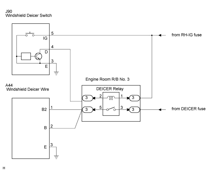

INSPECTION PROCEDURE
| 1. CHECK WIRE HARNESS (WINDSHIELD DEICER SWITCH) |

Disconnect the windshield deicer switch.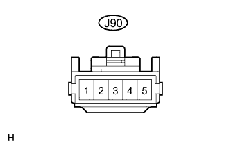
Measure the voltage and resistance according to the value(s) in the table below.
- Voltage:
Tester Connection
Condition
Specified Condition
J90-5 (IG) - Body ground
Engine switch on (IG)
10 to 14 V
- Resistance:
Tester Connection
Condition
Specified Condition
J90-3 - Body ground
Always
Below 1 Ω
|
|
||||

| OK | |
 |
| 2. INSPECT WINDSHIELD DEICER SWITCH |
Measure the voltage according to the value(s) in the table below (connector still connected).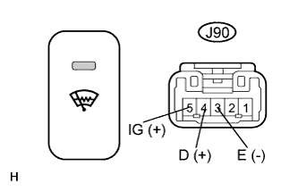
- Resistance:
Tester Connection
Condition
Specified Condition
J90-4 (D) - J90-3 (E)
Engine switch on (IG), windshield deicer switch OFF → ON
Below 1 V → 10 to 14 V
J90-5 (IG) - J90-3 (E)
Windshield deicer switch ON → OFF
10 to 14 V → Below 1 V
|
|
||||
| OK | |
|
| 3. SYSTEM CHECK |
Check that the indicator comes on after the engine switch has been turned on (IG) and the windshield deicer switch has been pressed.
- Result:
Indicator off
A
Indicator on
B
|
|
||||

| A | |
|
| 4. CHECK WIRE HARNESS (DEICER RELAY - BATTERY POSITIVE AND BODY GROUND) |
Disconnect the DEICER relay.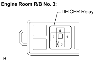
Measure the voltage according to the value(s) in the table below.
- Voltage:
- Engine Room R/B No. 3:
Tester Connection
Condition
Specified Condition
1 - Body ground
Engine switch on (IG)
10 to 14 V
|
|
||||
| OK | |
|
| 5. CHECK WIRE HARNESS (DEICER RELAY - WINDSHIELD DEICER SWITCH) |
Disconnect the DEICER relay and windshield deicer switch.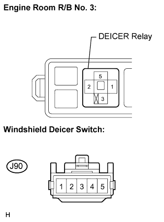
Measure the resistance according to the value(s) in the table below.
- Resistance:
Tester Connection
Condition
Specified Condition
2 - J90-4 (D)
Always
Below 1 Ω
2 - Body ground
Always
10 kΩ or higher
|
|
||||
| OK | ||
 |
||
| ||
| 6. CHECK WIRE HARNESS (DEICER RELAY - BATTERY POSITIVE AND BODY GROUND) |
Disconnect the DEICER relay.
Measure the voltage according to the value(s) in the table below.
- Voltage:
- Engine Room R/B No. 3:
Tester Connection
Condition
Specified Condition
3 - Body ground
Engine switch on (IG)
10 to 14 V
|
|
||||
| OK | |
|
| 7. CHECK WIRE HARNESS (DEICER RELAY - WINDSHIELD DEICER WIRE) |
Disconnect the DEICER relay and windshield deicer switch.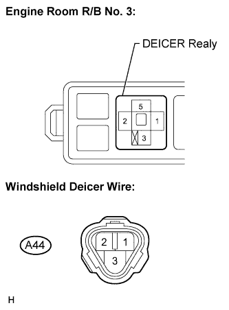
Measure the resistance according to the value(s) in the table below.
- Resistance:
Tester Connection
Condition
Specified Condition
5 - A44-1 (B2)
Always
Below 1 Ω
5 - A44-2 (B)
Always
Below 1 Ω
5 - Body ground
Always
10 kΩ or higher
|
|
||||
| OK | |
|
| 8. INSPECT WINDSHIELD DEICER RELAY |
|
|
||||
| OK | |
|
| 9. CHECK WIRE HARNESS (WINDSHIELD DEICER WIRE - BODY GROUND) |
Disconnect the windshield deicer wire.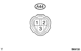
Measure the resistance according to the value(s) in the table below.
- Resistance:
Tester Connection
Condition
Specified Condition
A44-3 (E) - Body ground
Always
Below 1 Ω
|
|
||||
| OK | ||
|
||
| ||