Climate Control Seat System does not Operate
Circuit diagnosis
DESCRIPTION
The A/C amplifier assembly receives seat position signals when the engine switch is on (IG), and then transmits airflow amount signals to each seat climate blower.WIRING DIAGRAM
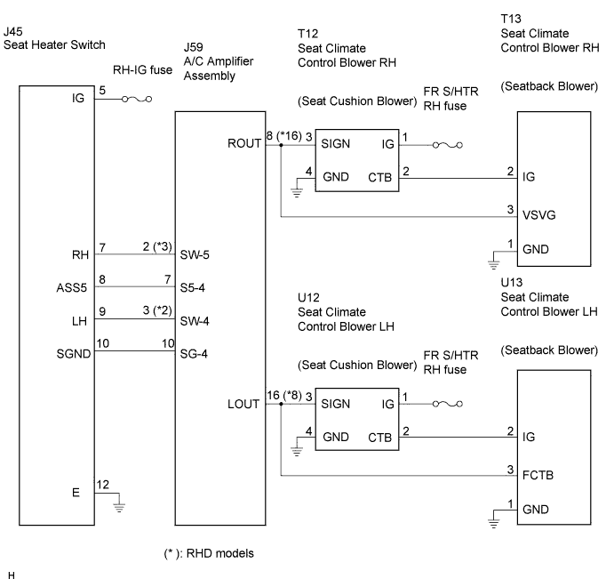

INSPECTION PROCEDURE
| 1. SYSTEM CHECK |

| Climate control seat does not operate (Front LH) |
A |
| Climate control seat does not operate (Front RH) |
B |
| Both climate control seats do not operate |
C |
|
|
||||
|
|
||||

| A | |
 |
| 2. CHECK WIRE HARNESS |
Disconnect the U12 connector.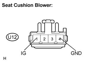
Measure the voltage and resistance according to the value(s) in the table below.
- Resistance:
Tester Connection
Condition
Specified Condition
U12-4 (GND) - Body ground
Always
Below 1 Ω
- Voltage:
Tester Connection
Condition
Specified Condition
U12-1 (IG) - Body ground
Engine switch on (IG)
10 to 14 V
Reconnect the U12 connector.
Disconnect the U13 connector.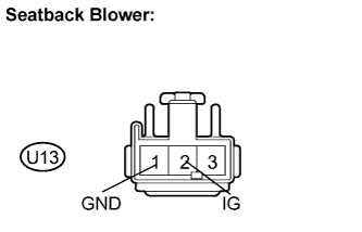
Measure the voltage and resistance according to the value(s) in the table below.
- Resistance:
Tester Connection
Condition
Specified Condition
U13-1 (GND) - Body ground
Always
Below 1 Ω
- Voltage:
Tester Connection
Condition
Specified Condition
U13-2 (IG) - Body ground
Engine switch on (IG)
10 to 14 V
|
|
||||

| OK | |
|
| 3. INSPECT SEAT CLIMATE CONTROL BLOWER |
Check the input signal waveform.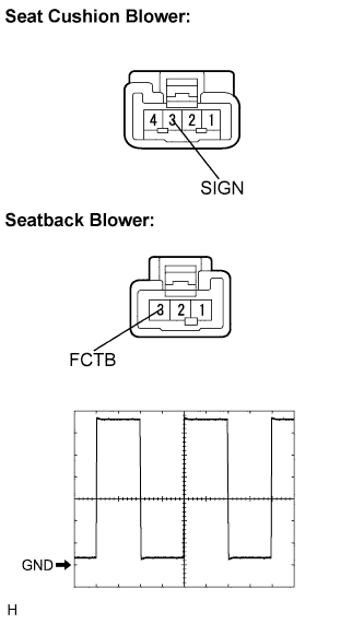
Connect the oscilloscope to terminal 3 and body ground with the climate control blower connector still connected.
Check the signal waveform according to the condition(s) in the table below.
Item
Condition
Tool setting
2 V/DIV., 500 μsec/DIV.,
Vehicle condition
Engine switch on (IG), seat heater switch ON
- OK:
- The waveform is displayed as shown in the illustration.
- Result:
NG
A
OK (Seat cushion blower side)
B
OK (Seatback blower side)
C
|
|
||||
|
|
||||
| A | |
|
| 4. CHECK WIRE HARNESS (A/C AMPLIFIER ASSEMBLY - SEAT CLIMATE CONTROL BLOWER) |
Disconnect the J59, U12 and U13 connectors.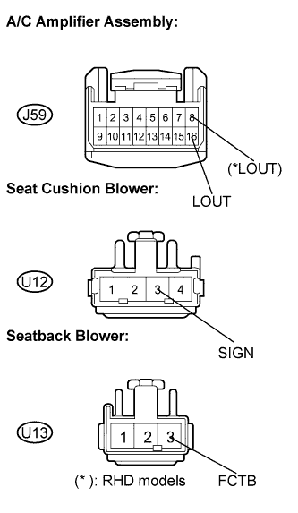
Measure the resistance according to the value(s) in the table below.
- Resistance:
- LHD models:
Tester Connection
Condition
Specified Condition
J59-16 (LOUT) - U12-3 (SIGN)
Always
Below 1 Ω
J59-16 (LOUT) - U13-3 (FCTB)
Always
Below 1 Ω
J59-16 (LOUT) - Body ground
Always
10 kΩ or higher
- RHD models:
Tester Connection
Condition
Specified Condition
J59-8 (LOUT) - U12-3 (SIGN)
Always
Below 1 Ω
J59-8 (LOUT) - U13-3 (FCTB)
Always
Below 1 Ω
J59-8 (LOUT) - Body ground
Always
10 kΩ or higher
|
|
||||
| OK | |
|
| 5. CHECK WIRE HARNESS (SEAT HEATER SWITCH) |
Disconnect the J45 connector.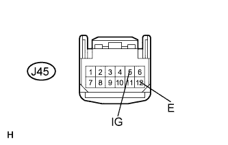
Measure the voltage and resistance according to the value(s) in the table below.
- Resistance:
Tester Connection
Condition
Specified Condition
J45-12 (E) - Body ground
Always
Below 1 Ω
- Voltage:
Tester Connection
Condition
Specified Condition
J45-5 (IG) - Body ground
Engine switch on (IG)
10 to 14 V
|
|
||||
| OK | |
|
| 6. INSPECT SEAT HEATER SWITCH |
Disconnect the J45 switch.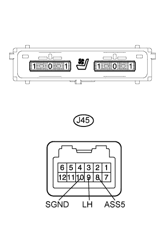
Measure the resistance according to the value(s) in the table below.
- Resistance:
Tester Connection
Condition
Specified Condition
J45-8 (ASS5) - J45-10 (SGND)
Always
Below 1 kΩ
J45-9 (LH) - J45-10 (SGND)
Blower switch OFF
Below 1.1 kΩ
Blower switch ON (Vol: 3)
Below 111 Ω
|
|
||||
| OK | |
|
| 7. CHECK WIRE HARNESS (SEAT HEATER SWITCH - A/C AMPLIFIER ASSEMBLY) |
Disconnect the J45 and J59 connectors.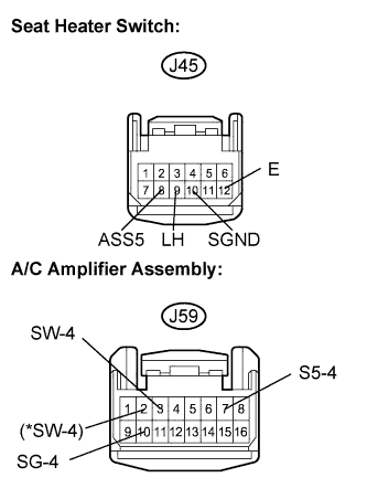
Measure the resistance according to the value(s) in the table below.(*): RHD models
- Resistance:
Tester Connection
Condition
Specified Condition
J45-8 (ASS5) - J59-7 (S5-4)
Always
Below 1 Ω
LHD models:
J45-9 (LH) - J59-3 (SW-4)
Always
Below 1 Ω
RHD models:
J45-9 (LH) - J59-2 (SW-4)
Always
Below 1 Ω
J45-10 (SGND) - J59-10 (SG-4)
Always
Below 1 Ω
J45-12 (E) - Body ground
Always
Below 1 Ω
J45-8 (ASS5) - Body ground
Always
10 kΩ or higher
J45-9 (LH) - Body ground
Always
10 kΩ or higher
|
|
||||
| OK | ||
 |
||
| ||
| 8. CHECK WIRE HARNESS |
Disconnect the T12 connector.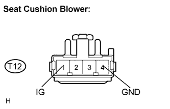
Measure the voltage and resistance according to the value(s) in the table below.
- Resistance:
Tester Connection
Condition
Specified Condition
T12-4 (GND) - Body ground
Always
Below 1 Ω
- Voltage:
Tester Connection
Condition
Specified Condition
T12-1 (IG) - Body ground
Engine switch on (IG)
10 to 14 V
Reconnect the T12 connector.
Disconnect the T13 connector.
Measure the voltage and resistance according to the value(s) in the table below.
- Resistance:
Tester Connection
Condition
Specified Condition
T13-1 (GND) - Body ground
Always
Below 1 Ω
- Voltage:
Tester Connection
Condition
Specified Condition
T13-2 (IG) - Body ground
Engine switch on (IG)
10 to 14 V
|
|
||||
| OK | |
|
| 9. INSPECT SEAT CLIMATE CONTROL BLOWER |
Check the input signal waveform.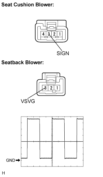
Connect the oscilloscope to terminal 3 and body ground with the climate control blower connector still connected.
Check the signal waveform according to the condition(s) in the table below.
Item
Condition
Tool setting
2 V/DIV., 500 μsec/DIV.,
Vehicle condition
Engine switch on (IG), seat heater switch ON
- OK:
- The waveform is displayed as shown in the illustration.
- Result:
NG
A
OK (Seat cushion blower side)
B
OK (Seatback blower side)
C
|
|
||||
|
|
||||
| A | |
|
| 10. CHECK WIRE HARNESS (A/C AMPLIFIER ASSEMBLY - SEAT CLIMATE CONTROL BLOWER) |
Disconnect the J59, T12 and T13 connectors.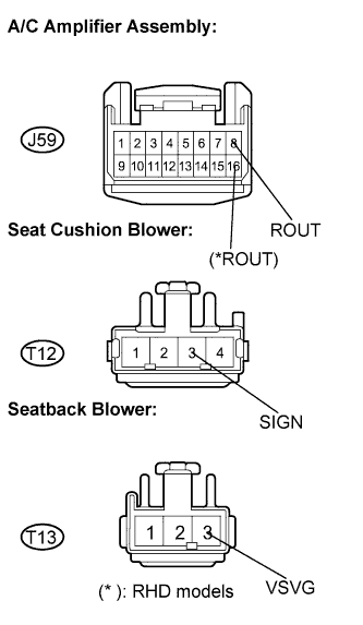
Measure the resistance according to the value(s) in the table below.
- Resistance:
- LHD models:
Tester Connection
Condition
Specified Condition
J59-8 (ROUT) - T12-3 (SIGN)
Always
Below 1 Ω
J59-8 (ROUT) - T13-3 (VSVG)
Always
Below 1 Ω
J59-8 (ROUT) - Body ground
Always
10 kΩ or higher
- RHD models:
Tester Connection
Condition
Specified Condition
J59-16 (ROUT) - T12-3 (SIGN)
Always
Below 1 Ω
J59-16 (ROUT) - T13-3 (VSVG)
Always
Below 1 Ω
J59-16 (ROUT) - Body ground
Always
10 kΩ or higher
|
|
||||
| OK | |
|
| 11. CHECK WIRE HARNESS (SEAT HEATER SWITCH) |
Disconnect the J45 connector.
Measure the voltage and resistance according to the value(s) in the table below.
- Resistance:
Tester Connection
Condition
Specified Condition
J45-12 (E) - Body ground
Always
Below 1 Ω
- Voltage:
Tester Connection
Condition
Specified Condition
J45-5 (IG) - Body ground
Engine switch on (IG)
10 to 14 V
|
|
||||
| OK | |
|
| 12. INSPECT SEAT HEATER SWITCH |
Disconnect the J45 switch.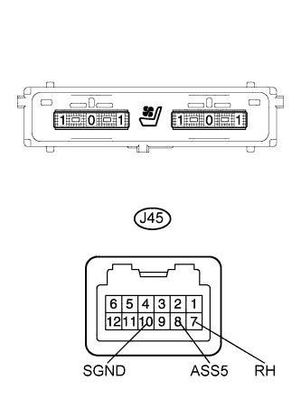
Measure the resistance according to the value(s) in the table below.
- Resistance:
Tester Connection
Condition
Specified Condition
J45-8 (ASS5) - J45-10 (SGND)
Always
Below 1 kΩ
J45-7 (RH) - J45-10 (SGND)
Blower switch OFF
Below 1.1 kΩ
Blower switch ON (Vol: 3)
Below 111 Ω
|
|
||||
| OK | |
|
| 13. CHECK WIRE HARNESS (SEAT HEATER SWITCH - A/C AMPLIFIER ASSEMBLY) |
Disconnect the J45 and J59 connectors.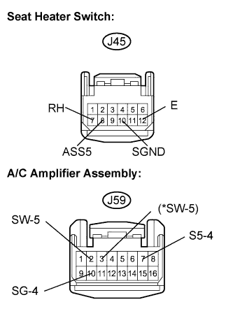
Measure the resistance according to the value(s) in the table below.(*): RHD models
- Resistance:
Tester Connection
Condition
Specified Condition
LHD models:
J45-7 (RH) - J59-2 (SW-5)
Always
Below 1 Ω
RHD models:
J45-7 (RH) - J59-3 (SW-5)
Always
Below 1 Ω
J45-8 (ASS5) - J59-7 (S5-4)
Always
Below 1 Ω
J45-10 (SGND) - J59-10 (SG-4)
Always
Below 1 Ω
J45-12 (E) - Body ground
Always
Below 1 Ω
J45-7 (RH) - J59-2 (SW-5)
Always
10 kΩ or higher
J45-8 (ASS5) - J59-7 (S5-4)
Always
10 kΩ or higher
|
|
||||
| OK | ||
|
||
| ||
| 14. CHECK WIRE HARNESS |
Disconnect the U12 (T12) connector.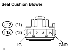
Measure the voltage and resistance according to the value(s) in the table below.
*2: Front RH
- Resistance:
- Front LH:
Tester Connection
Condition
Specified Condition
U12-4 (GND) - Body ground
Always
Below 1 Ω
- Front RH:
Tester Connection
Condition
Specified Condition
T12-4 (GND) - Body ground
Always
Below 1 Ω
- Voltage:
- Front LH:
Tester Connection
Condition
Specified Condition
U12-1 (IG) - Body ground
Engine switch on (IG)
10 to 14 V
- Front RH:
Tester Connection
Condition
Specified Condition
T12-4 (GND) - Body ground
Always
Below 1 Ω
Reconnect the U12 (T12) connector.
Disconnect the U13 (T13) connector.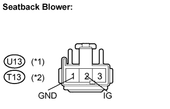
Measure the voltage and resistance according to the value(s) in the table below.
*2: Front RH
- Resistance:
- Front LH:
Tester Connection
Condition
Specified Condition
U13-1 (GND) - Body ground
Always
Below 1 Ω
- Front RH:
Tester Connection
Condition
Specified Condition
T13-1 (GND) - Body ground
Always
Below 1 Ω
- Voltage:
- Front LH:
Tester Connection
Condition
Specified Condition
U13-2 (IG) - Body ground
Engine switch on (IG)
10 to 14 V
- Front RH:
Tester Connection
Condition
Specified Condition
U13-2 (IG) - Body ground
Engine switch on (IG)
10 to 14 V
|
|
||||
| OK | |
|
| 15. INSPECT SEAT CLIMATE CONTROL BLOWER |
Check the input signal waveform.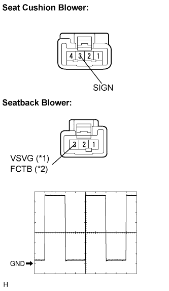
Connect the oscilloscope to terminal 3 and body ground with the climate control blower connector still connected.
Check the signal waveform according to the condition(s) in the table below.
Item
Condition
Tool setting
2 V/DIV., 500 μsec/DIV.,
Vehicle condition
Engine switch on (IG), seat heater switch ON
- OK:
- The waveform is displayed as shown in the illustration.
*2: Front RH
- Result:
NG
A
OK (Seat cushion blower side)
B
OK (Seatback blower side)
C
|
|
||||
|
|
||||
| A | |
|
| 16. CHECK WIRE HARNESS (A/C AMPLIFIER ASSEMBLY - SEAT CLIMATE CONTROL BLOWER) |
Disconnect the J59, U12 (T12) and U13 (T13) connectors.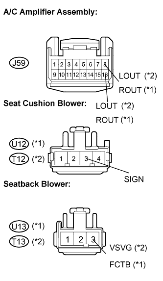
*2: Front RH
Measure the resistance according to the value(s) in the table below.
- Resistance:
- Front LH:
Tester Connection
Condition
Specified Condition
RHD models:
J59-8 (LOUT) - U12-3 (SIGN)
Always
Below 1 Ω
RHD models:
J59-8 (LOUT) - U13-3 (FCTB)
Always
Below 1 Ω
RHD models:
J59-8 (LOUT) - Body ground
Always
10 kΩ or higher
LHD models:
J59-16 (LOUT) - U12-3 (SIGN)
Always
Below 1 Ω
LHD models:
J59-16 (LOUT) - U13-3 (FCTB)
Always
Below 1 Ω
LHD models:
J59-16 (LOUT) - Body ground
Always
10 kΩ or higher
- Front RH:
Tester Connection
Condition
Specified Condition
LHD models:
J59-8 (ROUT) - T12-3 (SIGN)
Always
Below 1 Ω
LHD models:
J59-8 (ROUT) - T13-3 (VSVG)
Always
Below 1 Ω
LHD models:
J59-8 (ROUT) - Body ground
Always
10 kΩ or higher
RHD models:
J59-16 (ROUT) - T12-3 (SIGN)
Always
Below 1 Ω
RHD models:
J59-16 (ROUT) - T13-3 (VSVG)
Always
Below 1 Ω
RHD models:
J59-16 (ROUT) - Body ground
Always
10 kΩ or higher
|
|
||||
| OK | |
|
| 17. CHECK WIRE HARNESS (SEAT HEATER SWITCH) |
Disconnect the J45 connector.
Measure the voltage and resistance according to the value(s) in the table below.
- Resistance:
Tester Connection
Condition
Specified Condition
J45-12 (E) - Body ground
Always
Below 1 Ω
- Voltage:
Tester Connection
Condition
Specified Condition
J45-5 (IG) - Body ground
Engine switch on (IG)
10 to 14 V
|
|
||||
| OK | |
|
| 18. INSPECT SEAT HEATER SWITCH |
Disconnect the J45 switch.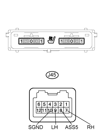
Measure the resistance according to the value(s) in the table below.
- Resistance:
- Front LH:
Tester Connection
Condition
Specified Condition
J45-8 (ASS5) - J45-10 (SGND)
Always
Below 1 kΩ
J45-9 (LH) - J45-10 (SGND)
Blower switch OFF
Below 1.1 kΩ
Blower switch ON (Vol: 3)
Below 111 Ω
- Front RH:
Tester Connection
Condition
Specified Condition
J45-8 (ASS5) - J45-10 (SGND)
Always
Below 1 kΩ
J45-7 (RH) - J45-10 (SGND)
Blower switch OFF
Below 1.1 kΩ
Blower switch ON (Vol: 3)
Below 111 Ω
|
|
||||
| OK | |
|
| 19. CHECK WIRE HARNESS (SEAT HEATER SWITCH - A/C AMPLIFIER ASSEMBLY) |
Disconnect the J45 and J59 connectors.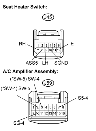
Measure the resistance according to the value(s) in the table below.(*): RHD models
- Resistance:
- Front LH:
Tester Connection
Condition
Specified Condition
J45-8 (ASS5) - J59-7 (S5-4)
Always
Below 1 Ω
LHD models:
J45-9 (LH) - J59-3 (SW-4)
Always
Below 1 Ω
RHD models:
J45-9 (LH) - J59-2 (SW-4)
Always
Below 1 Ω
J45-10 (SGND) - J59-10 (SG-4)
Always
Below 1 Ω
J45-12 (E) - Body ground
Always
Below 1 Ω
J45-8 (ASS5) - Body ground
Always
10 kΩ or higher
J45-9 (LH) - Body ground
Always
10 kΩ or higher
- Front RH:
Tester Connection
Condition
Specified Condition
LHD models:
J45-7 (RH) - J59-2 (SW-5)
Always
Below 1 Ω
RHD models:
J45-7 (RH) - J59-3 (SW-5)
Always
Below 1 Ω
J45-8 (ASS5) - J59-7 (S5-4)
Always
Below 1 Ω
J45-10 (SGND) - J59-10 (SG-4)
Always
Below 1 Ω
J45-12 (E) - Body ground
Always
Below 1 Ω
J45-7 (RH) - Body ground
Always
10 kΩ or higher
J45-8 (ASS5) - Body ground
Always
10 kΩ or higher
|
|
||||
| OK | ||
|
||
| ||