INSPECTION
Inspection
| INSPECT DOOR MIRROR FOOT LIGHT |

Disconnect the connector from the door mirror foot light.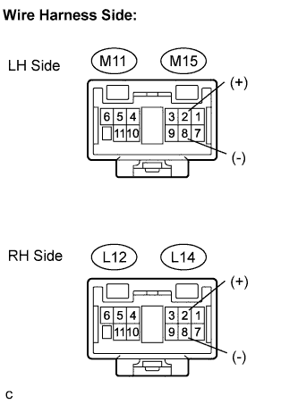

Measure the voltage of the connector.
- Standard voltage:
- LH Side (Without Seat Position Memory):
Tester Connection
Condition
Specified Condition
M11-2 (+) - M11-8 (-)
Doors unlock by the transmitter
10 to 14 V
M11-2 (+) - M11-8 (-)
All doors are locked
Below 1 V
- LH Side (With Seat Position Memory):
Tester Connection
Condition
Specified Condition
M15-2 (+) - M15-8 (-)
Doors unlock by the transmitter
10 to 14 V
M15-2 (+) - M15-8 (-)
All doors are locked
Below 1 V
- RH Side (Without Seat Position Memory):
Tester Connection
Condition
Specified Condition
L12-2 (+) - L12-8 (-)
Doors unlock by the transmitter
10 to 14 V
L12-2 (+) - L12-8 (-)
All doors are locked
Below 1 V
- RH Side (With Seat Position Memory):
Tester Connection
Condition
Specified Condition
L14-2 (+) - L14-8 (-)
Doors unlock by the transmitter
10 to 14 V
L14-2 (+) - L14-8 (-)
All doors are locked
Below 1 V
Connect the (+) lead from the battery to terminal 2 and the (-) lead to terminal 8.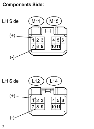
Check that the door mirror foot light comes on.
- OK:
- Comes on