Trouble in Passenger Airbag ON / OFF Indicator
Circuit diagnosis
DESCRIPTION
This circuit detects the manual cut off switch status.The passenger airbag ON/OFF indicator comes on to inform the passengers of the front passenger airbag assembly, front passenger side knee airbag assembly and the front seat side airbag assembly (passenger side) status (activated or deactivated).
- HINT:
- Approximately 6 seconds after the engine switch is turned to the on (IG), the passenger airbag ON/OFF indicator will be ON/OFF depending on the conditions listed below.
Manual cut off switch
Passenger airbag ON/OFF indicator
SRS Warning Light
ON indicator
OFF indicator
ON position
ON
OFF
OFF
OFF position
OFF
ON
OFF
Switch failure
OFF
ON
ON
INSPECTION PROCEDURE
| 1. CHECK SRS WARNING LIGHT |

Turn the engine switch on (IG), and check the SRS warning light condition.
- HINT:
- If this trouble occurs, the SRS warning light is off. If it is on, a DTC is output. Troubleshoot for the output DTC.
- OK:
- After the primary check period, SRS warning light goes off.
- HINT:
- The primary check period is approximately 6 seconds after the ignition switch is turned on (IG).
|
|
||||

| OK | |
 |
| 2. CHECK CONNECTION OF CONNECTORS |
Turn the engine switch off.
Disconnect the negative (-) terminal cable from the battery, and wait for at least 90 seconds.
Check that the connectors are properly connected to the center airbag sensor assembly and the airbag cut off switch cylinder.
- OK:
- The connectors are properly connected.
|
|
||||
| OK | |
|
| 3. CHECK INSTRUMENT PANEL WIRE (OPEN) |
Disconnect the connectors from the center airbag sensor assembly and the airbag cut off switch cylinder.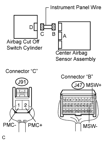

Measure the resistance according to the value(s) in the table below.
- Standard resistance:
Tester connection
Condition
Specified condition
J91-2 (PMC+) -
J91-1 (PMC-)
Always
Below 1 Ω
|
|
||||
| OK | |
|
| 4. CHECK INSTRUMENT PANEL WIRE (SHORT) |
Release the activation prevention mechanism built into connector "B".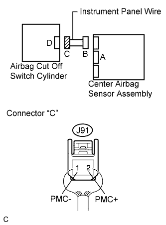
Measure the resistance according to the value(s) in the table below.
- Standard resistance:
Tester connection
Condition
Specified condition
J91-2 (PMC+) -
J91-1 (PMC-)
Always
1 MΩ or higher
|
|
||||
| OK | |
|
| 5. CHECK INSTRUMENT PANEL WIRE (SHORT TO GROUND) |
Measure the resistance according to the value(s) in the table below.
- Standard resistance:
Tester connection
Condition
Specified condition
J91-2 (PMC+) -
Body ground
Always
1 MΩ or higher
J91-1 (PMC-) -
Body ground
Always
1 MΩ or higher
|
|
||||
| OK | |
|
| 6. CHECK INSTRUMENT PANEL WIRE (SHORT TO B+) |
Connect the negative (-) terminal cable to the battery, and wait for at least 2 seconds.
Turn the engine switch on (IG).
Measure the resistance according to the value(s) in the table below.
- Standard voltage:
Tester connection
Condition
Specified condition
J91-2 (PMC+) -
Body ground
Engine switch on (IG)
Below 1 V
J91-1 (PMC-) -
Body ground
Engine switch on (IG)
Below 1 V
|
|
||||
| OK | |
|
| 7. CHECK AIRBAG CUT OFF SWITCH CYLINDER |
Turn the engine switch off.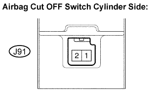
Disconnect the negative (-) terminal cable from the battery, and wait for at least 90 seconds.
Measure the resistance according to the value(s) in the table below.
- Standard resistance:
Tester connection
Manual cut off switch condition
Specified condition
J91-2 (PMC+) -
J91-1 (PMC-)
Cut off switch is in ON position
360 to 440 Ω
J91-2 (PMC+) -
J91-1 (PMC-)
Cut off switch is in OFF position
90 to 110 Ω
|
|
||||
| OK | ||
 |
||
| ||