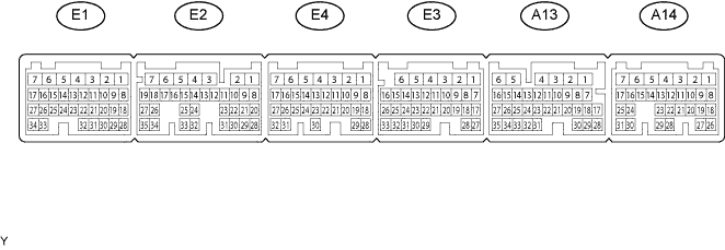
СИСТЕМА SFI > КОНТАКТЫ ECM |
| Terminal No. (Symbols) | Wiring Color | Terminal Description | Condition | Specified Condition |
| A14-7 (BATT) - E3-1 (E1) | B - W-B | Battery (for measuring battery voltage and for ECM memory) | Always | 11 to 14 V |
| E1-1 (+BM) - E3-1 (E1) | L - W-B | Power source of throttle actuator | Always | 11 to 14 V |
| A14-8 (IGSW) - E3-1 (E1) | R - W-B | Engine switch | Engine switch on (IG) | 11 to 14 V |
| A13-2 (+B) - E3-1 (E1) | B-W - W-B | Power source of ECM | Engine switch on (IG) | 11 to 14 V |
| A13-1 (+B1) - E3-1 (E1) | B-W - W-B | Power source of ECM | Engine switch on (IG) | 11 to 14 V |
| E2-4 (OE1+) - E2-3 (OE1-) | R - L-W | Camshaft timing oil control valve (OCV) (exhaust side [bank 1]) | Idling | Pulse generation (see waveform 1) |
| E4-18 (OE2+) - E4-28 (OE2-) | B-W - Y-B | Camshaft timing oil control valve (OCV) (exhaust side [bank 2]) | Idling | Pulse generation (see waveform 1) |
| A14-3 (MREL) - E3-1 (E1) | P - W-B | EFI MAIN1, EFI MAIN2 relay | Engine switch on (IG) | 11 to 14 V |
| E1-18 (VC) - E1-28 (E2) | L - BR | Power source for sensor (specific voltage) | Engine switch on (IG) | 4.5 to 5.0 V |
| E1-25 (VG) - E1-24 (E2G) | B-R - B-W | Mass air flow meter (bank 1) | Idling, Shift position in P or N, A/C switch OFF | 0.5 to 3.0 V |
| E1-23 (VG2) - E1-32 (E2G2) | B-R - B-W | Mass air flow meter (bank 2) | Idling, Shift lever position P or N, A/C switch OFF | 0.5 to 3.0 V |
| E1-22 (THA) - E1-28 (E2) | B-L - BR | Intake air temperature sensor (bank 1) | Idling, Intake air temperature (bank 1) 0 to 80°C (32 to 176°F) | 0.5 to 3.4 V |
| E1-21 (THA2) - E1-28 (E2) | B-L - BR | Intake air temperature sensor (bank 2) | Idling, Intake air temperature (bank 2) 0 to 80°C (32 to 176°F) | 0.5 to 3.4 V |
| E1-19 (THW) - E1-28 (E2) | R-L - BR | Engine coolant temperature sensor | Idling, Engine coolant temperature 60 to 80°C (140 to 176°F) | 0.2 to 1.0 V |
| E2-34 (VCTA) - E2-35 (ETA) | R - W | Power source for throttle position sensor (specific voltage) | Engine switch on (IG) | 4.5 to 5.0 V |
| E2-26 (VTA) - E2-35 (ETA) | G - W | Throttle position sensor (for engine control) | Engine switch on (IG), Throttle valve fully closed | 0.5 to 1.2 V |
| Engine switch on (IG), Throttle valve fully open | 3.2 to 4.8 V | |||
| E2-27 (VTA2) - E2-35 (ETA) | Y - W | Throttle position sensor (for sensor malfunction detection) | Engine switch on (IG), Accelerator pedal released | 2.1 to 3.1 V |
| Engine switch on (IG), Accelerator pedal released | 4.5 to 5.0 V | |||
| A14-29 (VPA) - A14-20 (EPA) | R - BR | Accelerator pedal position sensor (for engine control) | Engine switch on (IG), Accelerator pedal released | 0.5 to 1.1 V |
| Engine switch on (IG), Accelerator pedal depressed | 2.6 to 4.5 V | |||
| A14-28 (VPA2) - A14-21 (EPA2) | R - BR | Accelerator pedal position sensor (for sensor malfunctioning detection) | Engine switch on (IG), Accelerator pedal released | 1.2 to 2.0 V |
| Engine switch on (IG), Accelerator pedal depressed | 3.4 to 5.0 V | |||
| A14-23 (VCPA) - A14-20 (EPA) | L - BR | Power source of accelerator pedal position sensor (for VPA) | Engine switch on (IG) | 4.5 to 5.0 V |
| A14-22 (VCP2) - A14-21 (EPA2) | O - BR | Power source of accelerator pedal position sensor (for VPA2) | Engine switch on (IG) | 4.5 to 5.0 V |
| E3-3 (HT1A) - A13-5 (E03) E3-2 (HT2A) - A13-5 (E03) | R - W-B R - W-B | Front oxygen sensor heater | Engine switch on (IG) | 11 to 14 V |
| Idling | Pulse generation (see waveform 2) | |||
| E3-28 (OX1A) - E1-28 (E2) | B - BR | Front oxygen sensor | Engine switch on (IG) | 0.1 to 0.9 V |
| E3-27 (OX2A) - E1-28 (E2) | B - BR | Front oxygen sensor | Engine switch on (IG) | 0.1 to 0.9 V |
| A13-4 (HT1B) - A13-5 (E03) A13-3 (HT2B) - A13-5 (E03) | B - W-B GR - W-B | Rear heated oxygen sensor heater | Engine switch on (IG) | 11 to 14 V |
| Idling | Below 3.0 V | |||
| A13-26 (OX1B) - E1-28 (E2) A13-27 (OX2B) - E1-28 (E2) | G - BR W - BR | Rear heated oxygen sensor | Maintain engine speed at 2500 rpm for 2 minutes after warming up sensor | Pulse generation (see waveform 3) |
| E4-17 (#10) - E3-1 (E1) E2-11 (#20) - E3-1 (E1) E4-16 (#30) - E3-1 (E1) E2-10 (#40) - E3-1 (E1) E4-15 (#50) - E3-1 (E1) E2-9 (#60) - E3-1 (E1) E4-14 (#70) - E3-1 (E1) E2-8 (#80) - E3-1 (E1) | G - W-B B - W-B GR - W-B W - W-B L - W-B Y - W-B V - W-B R - W-B | Injector for port injection | Engine switch on (IG) | 11 to 14 V |
| Idling | Pulse generation (see waveform 4) | |||
| E3-26 (KNK1) - E3-33 (EKNK) | W - B | Knock sensor (bank 2 sensor 1) | Maintain engine speed at 4000 rpm after warming up | Pulse generation (see waveform 5) |
| E3-25 (KNK2) - E3-32 (EKN2) | G - R | Knock sensor (bank 1 sensor 1) | Maintain engine speed at 4000 rpm after warming up | Pulse generation (see waveform 5) |
| E3-24 (KNK3) - E3-31 (ENK3) | W - B | Knock sensor (bank 2 sensor 2) | Maintain engine speed at 4000 rpm after warming up | Pulse generation (see waveform 5) |
| E3-23 (KNK4) - E3-30 (ENK4) | G - R | Knock sensor (bank 1 sensor 2) | Maintain engine speed at 4000 rpm after warming up | Pulse generation (see waveform 5) |
| E2-25 (VV1+) - E2-33 (VV1-) | Y - R | Variable valve timing (VVT) sensor (intake side [bank 1]) | Idling | Pulse generation (see waveform 6) |
| E4-19 (VV2+) - E4-29 (VV2-) | R - W | Variable valve timing (VVT) sensor (intake side [bank 2]) | Idling | Pulse generation (see waveform 6) |
| E1-26 (EV1+) - E1-33 (EV1-) | Y - L-Y | Variable valve timing (VVT) sensor (exhaust side [bank 1]) | Idling | Pulse generation (see waveform 7) |
| E3-22 (EV2+) - E3-29 (EV2-) | B - BR | Variable valve timing (VVT) sensor (exhaust side [bank 2]) | Idling | Pulse generation (see waveform 7) |
| E2-24 (G2+) - E2-32 (G2-) | Y - R | Camshaft position sensor | Idling | Pulse generation (see waveform 8) |
| E1-27 (NE+) - E1-34 (NE-) | W - P | Crankshaft position sensor | Idling | Pulse generation (see waveform 8) |
| E4-27 (IGT1) - E3-1 (E1) E2-23 (IGT2) - E3-1 (E1) E4-26 (IGT3) - E3-1 (E1) E2-22 (IGT4) - E3-1 (E1) E4-25 (IGT5) - E3-1 (E1) E2-21 (IGT6) - E3-1 (E1) E4-24 (IGT7) - E3-1 (E1) E2-20 (IGT8) - E3-1 (E1) | G-B - W-B L-W - W-B L-Y - W-B LG - W-B R - W-B R-L - W-B P-L - W-B B-W - W-B | Ignition coil (ignition signal) | Idling | Pulse generation (see waveform 9) |
| E4-32 (IGF1) - E3-1 (E1) E2-28 (IGF2) - E3-1 (E1) | LG - W-B G-B - W-B | Ignition coil (ignition confirmation signal) | Engine switch on (IG) | 4.5 to 5.0 V |
| Idling | Pulse generation (see waveform 9) | |||
| E1-17 (PRG) - E3-1 (E1) | W-B - W-B | Purge VSV | Engine switch on (IG) | 11 to 14 V |
| Idling | Pulse generation (see waveform 10) | |||
| A14-24 (SPD) - E3-1 (E1) | V - W-B | Speed signal from combination meter | Engine switch on (IG), Rotate driving wheel slowly | Pulse generation (see waveform 11) |
| A13-20 (STA) - E3-1 (E1) | Y - W-B | ST relay operation signal | Cranking | 11 to 14 V |
| A14-2 (STAR) - E3-1 (E1) | BR - W-B | ST relay drive signal | Engine switch on (IG), Shift position other than P or N | 11 to 14 V |
| Cranking, Shift position in P or N | 0 to 3.0 V | |||
| A14-27 (STSW) - E3-1 (E1) | B - W-B | Engine cranking required signal | Cranking, Shift position in P or N | 6.0 V or more |
| A14-13 (STP) - E3-1 (E1) | L - W-B | Stop light switch | Brake pedal depressed | 7.5 to 14 V |
| Brake pedal released | Below 1.5 V | |||
| A14-12 (ST1-) - E3-1 (E1) | V - W-B | Stop light switch (opposite to STP terminal) | Engine switch on (IG), Brake pedal depressed | Below 1.5 V |
| Engine switch on (IG), Brake pedal released | 7.5 to 14 V | |||
| E2-7 (M+) - E2-5 (ME01) | W - W-B | Throttle actuator | Idling with warm engine | Pulse generation (see waveform 12) |
| E2-6 (M-) - E2-5 (ME01) | B - W-B | Throttle actuator | Idling with warm engine | Pulse generation (see waveform 13) |
| A14-5 (FC) - E3-1 (E1) | G - W-B | C/OPN relay | Engine switch on (IG) | 11 to 14 V |
| Idling | 0 to 3.0 V | |||
| A14-6 (FPR) - E3-1 (E1) | Y - W-B | F/PMP relay | Engine switch on (IG) | 11 to 14 V |
| A14-11 (W) - E3-1 (E1) | Y - W-B | MIL | Engine switch on (IG) | Below 3.0 V |
| Idling | 0 to 14 V | |||
| A13-21 (TC) - E3-1 (E1) | P - W-B | Terminal TC of DLC3 | Engine switch on (IG) | 11 to 14 V |
| A14-15 (TACH) - E3-1 (E1) | R - W-B | Engine speed | Idling | Pulse generation (see waveform 14) |
| A13-14 (CANH) - E3-1 (E1) | R - W-B | CAN communication line | Engine switch on (IG) | Pulse generation (see waveform 15) |
| A13-13 (CANL) - E3-1 (E1) | G - W-B | CAN communication line | Engine switch on (IG) | Pulse generation (see waveform 16) |
| E2-18 (ALT) - E3-1 (E1) | L-R - W-B | Generator M terminal | Engine switch on (IG) | 11 to 14 V |
| E2-17 (RLO) - E3-1 (E1) | G - W-B | Recharging control | Idling | Pulse generation (see waveform 17) |
| E4-7 (ASM+) - E4-6 (ASM-) | L - P | Intake air control valve actuator | Warm engine and 3,000 rpm | Pulse generation (see waveform 18) |
| A13-7 (SFTD) - E3-1 (E1) | L - W-B | Down-shift position switch signal | Engine switch on (IG) and shift lever on S | 11 to 14 V |
| Engine switch on (IG) and shift lever "-" position (down-shift) | Below 1 V | |||
| A13-8 (SFTU) - E3-1 (E1) | Y - W-B | Up-shift position switch signal | Engine switch on (IG) and shift lever on S | 11 to 14 V |
| Engine switch on (IG) and shift lever "+" position (up-shift) | Below 1 V | |||
| A13-16 (S) - E3-1 (E1) | G - W-B | S shift position switch signal | Engine switch on (IG) and shift lever on S | 11 to 14 V |
| Engine switch on (IG) and shift lever not on S | Below 1 V | |||
| A13-9 (CAN-) - E3-1 (E1) | W - W-B | Communication signal with TCM | Engine switch on (IG) | Pulse generation |
| A13-10 (CAN+) - E3-1 (E1) | B - W-B | Communication signal with TCM | Engine switch on (IG) | Pulse generation |
| A13-19 (ACCR) - E3-1 (E1) | G - W-B | D-ACC relay cut signal | Engine switch on (IG) → Cranking | 11 to 14 V → Below 1 V |
| A13-29 (NSW) - E3-1 (E1) | L - W-B | Park/Neutral position switch | Engine switch on (IG), shift position in P or N | Below 3.0 V |
| Engine switch on (IG), Shift position except P or N | 11 to 14 V | |||
| E3-11 (R) - E3-1 (E1) | G - W-B | Park/Neutral position switch signal | Engine switch on (IG) and Shift lever on R | 11 to 14 V |
| Engine switch on (IG) and Shift lever not on R | Below 1 V | |||
| E3-12 (P) - E3-1 (E1) | W - W-B | Park/Neutral position switch signal | Engine switch on (IG) and Shift lever on P | 11 to 14 V |
| Engine switch on (IG) and Shift lever not on P | Below 1 V | |||
| E3-13 (N) - E3-1 (E1) | G-R - W-B | Park/Neutral position switch signal | Engine switch on (IG) and Shift lever on N | 11 to 14 V |
| Engine switch on (IG) and Shift lever not on N | Below 1 V | |||
| E3-14 (D) - E3-1 (E3-1) | G-Y - W-B | Park/Neutral position switch signal | Engine switch on (IG) and Shift lever on D | 11 to 14 V |
| Engine switch on (IG) and Shift lever not on D | Below 1 V | |||
| E4-9 (EMD1) - E3-1 (E1) | W - W-B | Camshaft timing control motor signal | Idling | Pulse generation (see waveform 19) |
| E2-31 (EMD2) - E3-1 (E1) | W-R - W-B | Camshaft timing control motor signal | Idling | Pulse generation (see waveform 19) |
| E4-30 (EMR1) - E3-1 (E1) | Y - W-B | Camshaft timing control motor signal | Idling | Pulse generation (see waveform 20) |
| E2-29 (EMR2) - E3-1 (E1) | Y-B - W-B | Camshaft timing control motor signal | Idling | Pulse generation (see waveform 20) |
| E4-8 (EDT1) - E3-1 (E1) | R - W-B | Camshaft timing control motor signal | Idling | Pulse generation (see waveform 21) |
| E2-16 (EDT2) - E3-1 (E1) | G-R - W-B | Camshaft timing control motor signal | Idling | Pulse generation (see waveform 21) |
| E4-31 (EMF1) - E3-1 (E1) | G - W-B | Camshaft timing control motor signal | Idling | 0.3 to 1.3 V |
| E2-30 (EMF2) - E3-1 (E1) | G-W - W-B | Camshaft timing control motor signal | Idling | 0.3 to 1.3 V |
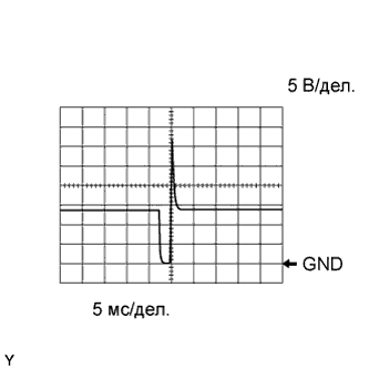
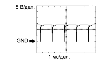
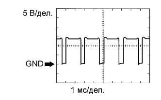
| WAVEFORM 1 |
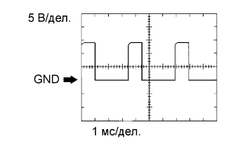 |
| ECM Terminal Name | Between OE1+ and OE1- or OE2+ and OE2- |
| Tester Range | 5 V/DIV., 1 msec./DIV. |
| Condition | Idling with warm engine |
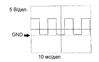
| WAVEFORM 2 |
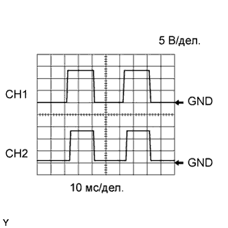 |
| ECM Terminal Name | CH1: Between HT1A and E1 CH2: Between HT2A and E1 |
| Tester Range | 5 V/DIV., 10 msec./DIV. |
| Condition | Idling with warm engine |
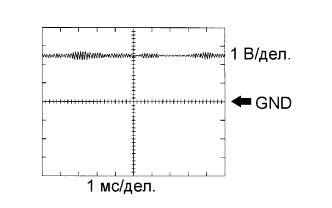
| WAVEFORM 3 |
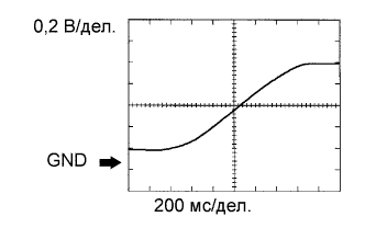 |
| ECM Terminal Name | Between OX1B and E2 or OX2B and E2 |
| Tester Range | 0.2 V/DIV., 200 msec./DIV. |
| Condition | Engine speed maintained at 2500 rpm for 2 minutes after warming up |
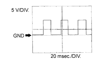
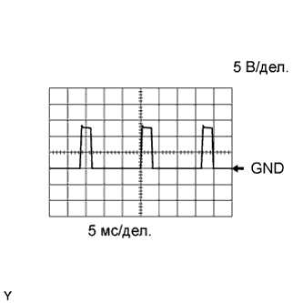
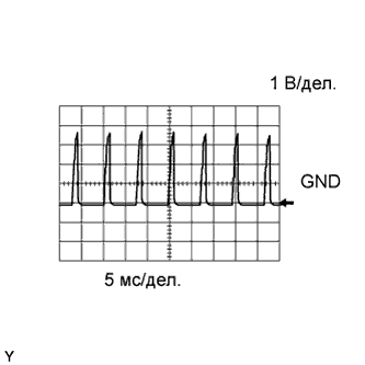
| WAVEFORM 4 |
 |
| ECM Terminal Name | Between #10 (to #80) and E1 |
| Tester Range | 5 V/DIV., 5 msec./DIV. |
| Condition | Idling |
| WAVEFORM 5 |
 |
| ECM Terminal Name | Between KNK1 and EKNK Between KNK2 and EKN2 Between KNK3 and ENK3 Between KNK4 and ENK4 |
| Tester Range | 0.01 to 10 V/DIV., 0.01 to 10 msec./DIV. |
| Condition | Engine speed maintained at 4000 rpm after warming up engine |
| WAVEFORM 6 |
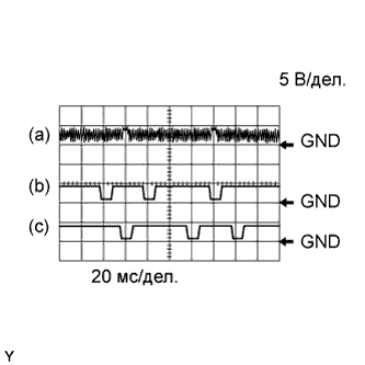 |
| ECM Terminal Name | (a) Between NE+ and NE- (b) Between VV1+ and VV1- (c) Between VV2+ and VV2- |
| Tester Range | 5 V/DIV., 20 msec./DIV. |
| Condition | Idling with warm engine |
| WAVEFORM 7 |
 |
| ECM Terminal Name | (a) Between NE+ and NE- (b) Between EV1+ and EV1- (c) Between EV2+ and EV2- |
| Tester Range | 5 V/DIV., 20 msec./DIV. |
| Condition | Idling with warm engine |
| WAVEFORM 8 |
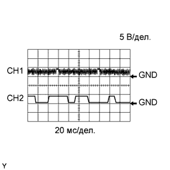 |
| ECM Terminal Name | CH1: Between NE+ and NE- CH2: Between G2+ and G2- |
| Tester Range | 5 V/DIV., 20 msec./DIV. |
| Condition | Idling with warm engine |
| WAVEFORM 9 |
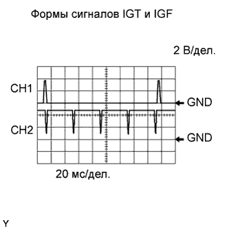 |
| ECM Terminal Name | CH1: Between IGT (1 to 8) and E1 CH2: Between IGF1 and E1 or IGF2 and E1 |
| Tester Range | 2 V/DIV., 20 msec./DIV. |
| Condition | Idling with warm engine |
| WAVEFORM 10 |
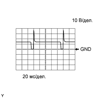 |
| ECM Terminal Name | Between PRG and E1 |
| Tester Range | 10 V/DIV., 20 msec./DIV. |
| Condition | Idling with warm engine |
| WAVEFORM 11 |
 |
| ECM Terminal Name | Between SPD and E1 |
| Tester Range | 2 V/DIV., 20 msec./DIV. |
| Condition | Driving at 12 mph (20 km/h) |
| WAVEFORM 12 |
 |
| ECM Terminal Name | Between M+ and ME01 |
| Tester Range | 5 V/DIV., 1 msec./DIV. |
| Condition | Idling with warm engine |
| WAVEFORM 13 |
 |
| ECM Terminal Name | Between M- and ME01 |
| Tester Range | 5 V/DIV., 1 msec./DIV. |
| Condition | Idling with warm engine |
| WAVEFORM 14 |
 |
| ECM Terminal Name | Between TACH and E1 |
| Tester Range | 5 V/DIV., 10 msec./DIV. |
| Condition | Idling |
| WAVEFORM 15 |
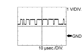 |
| ECM Terminal Name | Between CANH and E1 |
| Tester Range | 1 V/DIV., 10 μsec./DIV. |
| Condition | Stop engine and Engine switch on (IG) |
| WAVEFORM 16 |
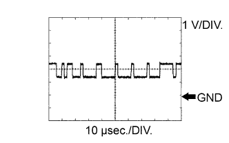 |
| ECM Terminal Name | Between CANL and E1 |
| Tester Range | 1 V/DIV., 10 μsec./DIV. |
| Condition | Stop engine and Engine switch on (IG) |
| WAVEFORM 17 |
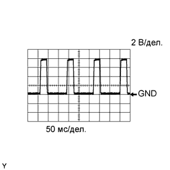 |
| ECM Terminal Name | Between RLO and E1 |
| Tester Range | 2 V/DIV., 50 msec./DIV. |
| Condition | Idling |
| WAVEFORM 18 |
 |
| ECM Terminal Name | Between ASM+ and ASM- |
| Tester Range | 5 V/DIV., 5 msec./DIV. |
| Condition | Warm engine and 3,000 rpm |
| WAVEFORM 19 |
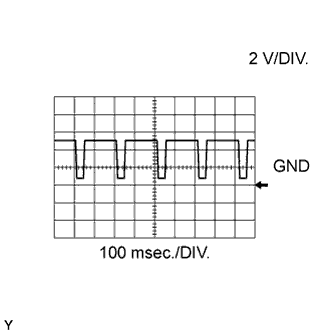 |
| ECM Terminal Name | Between EMD1 and E1 or EMD2 and E1 |
| Tester Range | 2 V/DIV., 100 msec./DIV. |
| Condition | Idling with warm engine |
| WAVEFORM 20 |
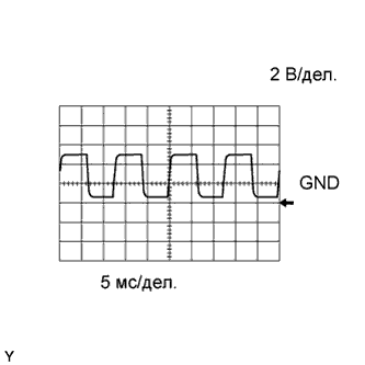 |
| ECM Terminal Name | Between EMR1 and E1 or EMR2 and E1 |
| Tester Range | 2 V/DIV., 5 msec./DIV. |
| Condition | Idling with warm engine |
| WAVEFORM 21 |
 |
| ECM Terminal Name | Between EDT1 and E1 or EDT2 and E1 |
| Tester Range | 1 V/DIV., 5 msec./DIV. |
| Condition | Idling with warm engine |
