СИСТЕМА SFI > РЕЖИМЫ DATA LIST / ACTIVE TEST |
| DATA LIST |
Warm up the engine.
Turn the engine switch off.
Connect the intelligent tester to the DLC3.
Turn the engine switch on (IG).
Turn the tester ON.
Enter the following menus: Powertrain / Engine / Data List.
Check the values by referring to the table below.
| Tester Display | Measurement Item/Range | Normal Condition | Diagnostic Note |
| Injector | Injection period of No. 1 cylinder: Min.: 0 ms, Max.: 32.64 ms | 0 to 2.0 msec.: Idling | - |
| IGN Advance | Ignition timing advance for No. 1 cylinder: Min.: -64 deg., Max.: 63.5 deg. | BTDC 5 to 22° : Idling | - |
| Calculate Load | Calculated load by ECM: Min.: 0%, Max.: 100% |
| - |
| Vehicle Load | Vehicle load: Min.: 0%, Max.: 25700% | Actual vehicle load | - |
| MAF | Air flow rate from MAF meter: Min.: 0 g/s , Max.: 655.35 g/s | 4.0 to 6.0 g/s: Idling 12.0 to 16.0 g/s: 2000 rpm 18.0 to 22.0 g/s: 3000 rpm | If value approximately 0.0 g/s:
|
| Engine Speed | Engine speed: Min.: 0 rpm, Max.: 16,383.75 rpm: | 700 to 800 rpm: Idling | - |
| Vehicle Speed | Vehicle speed: Min.: 0 km/h, Max.: 255 Km/h | Actual vehicle speed | Speed indicated on speedometer |
| Coolant Temp | Engine coolant temperature: Min.: -40°C, Max.: 140°C | 80 to 105°C (176 to 221°F): After warming up |
|
| Intake Air | Intake air temperature: Min.: -40°C, Max.: 140°C | Equivalent to ambient air temperature |
|
| Air-Fuel Ratio | Air-fuel ratio: Min.: 0 ,Max.: 1.999 | 0.8 to 1.2 : During idling | - |
| Purge Density Learn Value | Learning value of purge density: Min.: -50, Max.: 350 | Idling: -35 to 1% | Service data |
| Evap Purge Flow | Purge flow: Min. : 0%, Max.: 102.4% | 0 to 4%: Idling | Service data |
| EVAP (Purge) VSV | VSV for EVAP control duty: Min.: 0%, Max.: 100% | 10 to 50%: During Idling | Active Test support data |
| Knock Correct Learn Value | Correction learning value of knocking: Min: -64 CA, Max.: 1,984 CA | 3 to 31.5°CA: Driving at 70 km/h (44 mph) | Service data |
| Knock Feedback Value | Feedback value of knocking: Min: -64 CA, Max.: 1,984 CA | -31.5 to 0°CA: Driving at 70 km/h (44 mph) | Service data |
| Clutch Current | Clutch current: Min.: 0 A, Max.: 2.49 A | - | - |
| MAF Bank 1 | Air flow rate from MAF meter bank 1: Min.: 0 g/sec., Max.: 655.35 g/sec. | 0.8 to 4.8 g/s: Idling 2.4 to 12.8 g/s: 2000 rpm 3.6 to 17.6 g/s: 3000 rpm | If value approximately 0.0 g/s:
|
| MAF Bank 2 | Air flow rate from MAF meter bank 2: Min.: 0 g/sec., Max.: 655.35 g/sec. | 0.8 to 4.8 g/s: Idling 2.4 to 12.8 g/s: 2000 rpm 3.6 to 17.6 g/s: 3000 rpm | If value approximately 0.0 g/s:
|
| Intake Air Bank 1 | Intake air temperature bank 1: Min.: -40°C, Max.: 140°C | Equivalent to ambient air temperature |
|
| Intake Air Bank 2 | Intake air temperature bank 2: Min.: -40°C, Max.: 140°C | Equivalent to ambient air temperature |
|
| Accelerator Position No. 1 | Absolute Accelerator Pedal Position (APP) No. 1: Min.: 0%, Max.: 100% | 10 to 25%: accelerator pedal released 60 to 90%: accelerator pedal fully depressed | - |
| Accelerator Position No. 2 | Absolute APP No.2: Min.: 0%, Max.: 100% | 20 to 45%: accelerator pedal released 80 to 100%: accelerator pedal fully depressed | - |
| Accelerator Position No. 1 | APP sensor No. 1 voltage: Min.: 0 V, Max.: 4.98 V | 0.5 to 1.1 V: accelerator pedal released 3.2 to 4.8 V: accelerator pedal fully depressed. | ETCS freeze data |
| Accelerator Position No. 2 | APP sensor No. 2 voltage: Min.: 0 V, Max.: 4.98 V | 2.1 to 3.1 V: accelerator pedal released 4.5 to 4.98 V: accelerator pedal fully depressed. | ETCS freeze data |
| Accelerator Position No. 1 | APP sensor No. 1 voltage: Min.: 0 V, Max.: 5 V | 0.4 to 1.4 V: accelerator pedal released 3.1 to 4.6 V: accelerator pedal fully depressed. | - |
| Accelerator Position No. 2 | APP sensor No. 2 voltage: Min.: 0 V, Max.: 5 V | 1.0 to 2.2 V: accelerator pedal released 3.9 to 5.0 V: accelerator pedal fully depressed. | - |
| Accelerator Idle Position | Whether or not accelerator pedal position sensor detecting idle: ON or OFF | ON: Idling | - |
| Throttle Fully Close Learn | Throttle valve fully closed (learned value): Min.: 0 V, Max.: 5 V | 0.4 to 0.8 V | - |
| Accel Fully Close #1 (AD) | Accelerator fully closed value No. 1 (AD): Min.: 0 V, Max.: 4.98 V | - | ETCS service data |
| Accel Fully Close Learn #1 | Accelerator fully closed learning value No. 1: Min.: 0 V, Max.: 124.512 V | - | ETCS service data |
| Accel Fully Close Learn #2 | Accelerator fully closed learning value No. 2: Min.: 0 V, Max.: 124.512 V | - | ETCS service data |
| Fail Safe Drive | Whether or not fail safe function executed: ON or OFF | ON: ETCS has failed | - |
| Fail Safe Drive (Main CPU) | Whether or not fail safe function executed: ON or OFF | ON: ETCS has failed | - |
| ST1 | Brake pedal: ON or OFF | ON: Released OFF: Depressed | - |
| System Guard | System guard: ON or OFF | - | ETCS service data |
| Open Side Malfunction | Open side malfunction: ON or OFF | - | ETCS service data |
| Throttle Position | Throttle position: Min.: 0%, Max.: 100% | 10 to 22%: Idling | Calculated value based on VTA1 |
| Throttle Idle Position | Whether or not throttle position sensor detecting idle: ON or OFF | ON: Idling | - |
| Throttle Require Position | Throttle requirement position: Min.: 0 V, Max.: 5 V | 0.5 to 1.0 V: Idling | - |
| Throttle Sensor Position | Throttle sensor position: Min.: 0%, Max.: 100% |
| Recognition value for throttle opening angle on ECM |
| Throttle Sensor Position #2 | Throttle sensor position #2 Min.: 0%, Max.: 100% | - | Calculated value based on VTA2 |
| Throttle Position No. 1 | Throttle position sensor No. 1 output voltage: Min.: 0 V, Max.: 4.98 V | - | ETCS freeze data |
| Throttle Position No. 2 | Throttle position sensor No. 2 output voltage: Min.: 0 V, Max.: 4.98 V | - | ETCS freeze data |
| Throttle Position No. 1 | Throttle position No. 1: Min.: 0 V, Max.: 5 V |
| - |
| Throttle Position No. 2 | Throttle position No. 2: Min.: 0 V, Max.: 5 V |
| - |
| Throttle Position Command | Throttle position command value: Min.: 0 V, Max.: 4.9804 V | 0.5 to 4.8 V | ETCS service data |
| Throttle Sens Open Pos #1 | Throttle sensor opener position No. 1: Min.: 0 V, Max.: 4.9804 V | 0.6 to 0.9 V | ETCS service data |
| Throttle Sens Open Pos #2 | Throttle sensor opener position No. 2: Min.: 0 V, Max.: 4.9804 V | 2.2 to 2.6 V | ETCS service data |
| Throttle Sens Open #1 (AD) | Throttle sensor opener position No. 1 (AD): Min.: 0 V, Max.: 4.9804 V | 0.6 to 0.9 V | ETCS service data |
| Throttle Motor | Whether or not throttle actuator control permitted: ON or OFF | ON: Idling | Read value with engine switch on (IG) (Do not start engine) |
| Throttle Motor Current | Throttle actuator current: Min.: 0 A, Max.: 80 A | 0 to 3.0 A: Idling | - |
| Throttle Motor | Throttle actuator: Min.: 0%, Max.: 100% | 10 to 20%: Idling | - |
| Throttle Motor Current | Throttle actuator current: Min.: 0 A, Max.: 19.92 A | 0 to 3.0 A: Idling | - |
| Throttle Motor Open Duty | Throttle actuator opening duty ratio: Min.: 0%, Max.: 100% | 0 to 40%: During idling | When accelerator pedal depressed, duty ratio increased |
| Throttle Motor Close Duty | Throttle actuator closed duty ratio: Min.: 0%, Max.: 100% | 0 to 40%: During idling | When accelerator pedal released quickly, duty ratio increased |
| Throttle Motor Duty (Open) | Throttle actuator duty ratio (open): Min.: 0%, Max.: 100% | 0 to 40%: During idling | ETCS service data |
| Throttle Motor Duty (Close) | Throttle actuator duty ratio (close): Min.: 0%, Max.: 100% | 0 to 40%: During idling | ETCS service data |
| O2S B1 S1 | Heated oxygen sensor output voltage for bank 1 sensor 1: Min.: 0 V Max.: 1.275 V | 0.1 to 0.9 V | - |
| O2S B2 S1 | Heated oxygen sensor output voltage for bank 2 sensor 1: Min.: 0 V Max.: 1.275 V | 0.1 to 0.9 V | - |
| O2S B1 S2 | Heated oxygen sensor output voltage for bank 1 sensor 2: Min.: 0 V Max.: 1.275 V | 0.1 to 0.9 V: Driving at 70 km/h (44 mph) | Performing Control the Injection Volume or Control the Injection Volume for A/F Sensor function of Active Test enables technician to check output voltage of sensor |
| O2S B2 S2 | Heated oxygen sensor output voltage for bank 2 sensor 2: Min.: 0 V Max.: 1.275 V | 0.1 to 0.9 V: Driving at 70 km/h (44 mph) | Performing Control the Injection Volume or Control the Injection Volume for A/F Sensor function of Active Test enables technician to check output voltage of sensor |
| Total FT #1 | Total fuel trim of bank 1 Average value for fuel trim system of bank 1: Min.: -0.5, Max.: 0.496 | -0.28 to 0.2: Idling | - |
| Total FT #2 | Total fuel trim of bank 1 Average value for fuel trim system of bank 2: Min.: -0.5, Max.: 0.496 | -0.28 to 0.2: Idling | - |
| Short FT #1 | Short-term fuel trim of bank 1: Min.: -100%, Max.: 99.2% | -20 to 20% | Short-term fuel compensation used to maintain air-fuel ratio at stoichiometric air-fuel ratio |
| Long FT #1 | Long-term fuel trim of bank 1: Min.: -100%, Max.: 99.2% | -30 to 30% | Overall fuel compensation carried out in long-term to compensate continual deviation of short-term fuel trim from central value |
| Short FT #2 | Short-term fuel trim of bank 2: Min.: -100%, Max.: 99.2% | -20 to 20% | Short-term fuel compensation used to maintain air-fuel ratio at stoichiometric air-fuel ratio |
| Long FT #2 | Long-term fuel trim of bank 2: Min.: -100%, Max.: 99.2% | -30 to 30% | Overall fuel compensation carried out in long-term to compensate continual deviation of short-term fuel trim from central value |
| Fuel System Status (Bank 1) | OL or CL or OL DRIVE or OL FAULT or CL FAULT | CL: Idling after warming up |
|
| Fuel System Status (Bank 2) | OL or CL or OL DRIVE or OL FAULT or CL FAULT | CL: Idling after warming up |
|
| O2FT B1 S1 | Short-term fuel trim (bank 1): -100 to 99.2% | 0 +-20% | - |
| O2FT B2 S1 | Short-term fuel trim (bank 2): -100 to 99.2% | 0 +-20% | - |
| O2 LR B1 S1 | Heated oxygen sensor (bank 1 sensor 1) voltage LEAN to RICH switching time: Min.: 0 msec., Max.: 16,711.68 msec. | Within 1 second | - |
| O2 LR B2 S1 | Heated oxygen sensor (bank 2 sensor 1) voltage LEAN to RICH switching time: Min.: 0 msec., Max.: 16,711.68 msec. | Within 1 second | - |
| O2 RL B1 S1 | Heated oxygen sensor (bank 1 sensor 1) voltage RICH to LEAN switching time Min.: 0 msec., Max.: 16,711.68 msec. | Within 1 second | - |
| O2 RL B2 S1 | Heated oxygen sensor (bank 2 sensor 1) voltage RICH to LEAN switching time Min.: 0 msec., Max.: 16,711.68 msec. | Within 1 second | - |
| Catalyst Temp (B1 S1) | Catalyst temperature (bank 1, sensor 1): Min.: -40°C, Max.: 6,513.5°C | - | - |
| Catalyst Temp (B2 S1) | Catalyst temperature (bank 2, sensor 1): Min.: -40°C, Max.: 6,513.5°C | - | - |
| Catalyst Temp (B1 S2) | Catalyst temperature (bank 1, sensor 2): Min.: -40°C, Max.: 6,513.5°C | - | - |
| Catalyst Temp (B2 S2) | Catalyst temperature (bank 2, sensor 2): Min.: -40°C, Ma 6,513.5°C | - | - |
| Sub O2S Impedance B1 S2 | Sub O2 sensor (bank 1) Min.: 0 Ω, Max,: 21,247.68 Ω | 5 to 15000 Ω | After driving approx. 10 min. in urban area |
| Sub O2S Impedance B2 S2 | Sub O2 sensor (bank 2) Min.: 0 Ω, Max,: 21,247.68 Ω | 5 to 15000 Ω | After driving approx. 10 min. in urban area |
| Initial Engine Coolant Temp | Initial engine coolant temperature: Min.: -40°C, Max.: 120°C | Coolant temperature when engine started | Service data |
| Initial Intake Air Temp | Initial intake air temperature: Min.: -40°C, Max.: 120°C | Intake air temperature when engine started | Service data |
| Injector Volum (Cylinder 1) | Injection volume (Cylinder 1): Min.: 0 ml, Max.: 2.048 ml | 0.05 to 0.15 ml/idling | Quantity of fuel injection volume for 10 times |
| ACC Relay | ACC relay: ON or OFF | ON: Cranking | - |
| Starter Relay | Starter relay: ON or OFF | ON: Cranking | - |
| Starter Signal | Starter signal: ON or OFF | ON: Cranking | - |
| Stater Control | Starter switch status: ON or OFF | ON: Cranking | - |
| Closed Throttle Position SW | Closed throttle position switch: ON or OFF |
| - |
| A/C Signal | A/C signal: ON or OFF | ON: A/C ON | - |
| Neutral Position SW Signal | PNP switch status ON or OFF | ON: P or N position | - |
| Electrical Load Signal | Electrical load signal: ON or OFF | ON: Headlights or defogger turned ON | - |
| Stop Light Switch | Stop light switch: ON or OFF | ON: Brake pedal depressed | - |
| Fuel Cut Condition | Fuel cut condition ON or OFF | ON: Fuel cut operating | - |
| ETCS Actuator Power | Whether or not electric throttle control system power inputted: ON or OFF | ON: Idling | - |
| +BM Voltage | +BM voltage: Min.: 0 V, Max.: 19.922 V | 11 to 14 V: Idling | ETCS service data |
| Battery Voltage | Battery voltage: Min.: 0 V, Max.: 65.535 V | 11 to 14 V: Idling | - |
| Actuator Power Supply | Actuator power supply: ON or OFF | ON: Idling | ETCS service data |
| Atmosphere Pressure | Atmospheric pressure: Min.: 1 kPa, Max.: 255 kPa | Equivalent to atmospheric pressure (absolute pressure) | - |
| Battery Current | Battery current: Min.: -100 A, Max.: 100 A | - | Refer to ELECTRIC POWER CONTROL SYSTEM |
| Battery Temperature | Battery temperature: Min.: -45 °C, Max.: 156.4 °C | - | Refer to ELECTRIC POWER CONTROL SYSTEM |
| Alternator Output Duty | Generator output duty ratio: Min.: 0%, Max.: 100% | - | During charge control Refer to ELECTRIC POWER CONTROL SYSTEM |
| Alt Vol - Non Active Test | Request output voltage: Min.: 0 V, Max.: 20 V | 11 to 14 V | Not during alternator forced activation Refer to ELECTRIC POWER CONTROL SYSTEM |
| Alt Vol - Active Test | Request output voltage: Min.: 0 V, Max.: 20 V | - | During alternator forced activation Refer to ELECTRIC POWER CONTROL SYSTEM |
| Fuel Pump Speed Control | Fuel pump speed control status: ON or OFF | Idling: ON | Active Test |
| ACIS VSV | ACIS VSV ON or OFF | - | Active Test support data |
| EVAP Purge VSV | VSV status for EVAP control: ON or OFF | - | - |
| Fuel Pump / Speed Status | Fuel pump/status: ON or OFF | ON: Cranking | Active Test support data |
| Electric Fan Motor | Electric fan motor: ON or OFF | ON: Electric fan motor operating | Active Test support data |
| TC and TE1 | TC and TE1 terminal of DLC3: ON or OFF | - | Active Test support data |
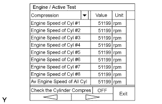
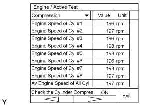
| Engine Speed of Cyl #1 | Engine rpm during No. 1 cylinder fuel cut: Min.: 0 rpm, Max.: 25600 rpm | - | Active Test support data |
| Engine Speed of Cyl #2 | Engine rpm during No. 2 cylinder fuel cut: Min.: 0 rpm, Max.: 25600 rpm | - | Active Test support data |
| Engine Speed of Cyl #3 | Engine rpm during No. 3 cylinder fuel cut: Min.: 0 rpm, Max.: 25600 rpm | - | Active Test support data |
| Engine Speed of Cyl #4 | Engine rpm during No. 4 cylinder fuel cut: Min.: 0 rpm, Max.: 25600 rpm | - | Active Test support data |
| Engine Speed of Cyl #5 | Engine rpm during No. 5 cylinder fuel cut: Min.: 0 rpm, Max.: 25600 rpm | - | Active Test support data |
| Engine Speed of Cyl #6 | Engine rpm during No. 6 cylinder fuel cut: Min.: 0 rpm, Max.: 25600 rpm | - | Active Test support data |
| Engine Speed of Cyl #7 | Engine rpm during No. 7 cylinder fuel cut: Min.: 0 rpm, Max.: 25600 rpm | - | Active Test support data |
| Engine Speed of Cyl #8 | Engine rpm during No. 8 cylinder fuel cut: Min.: 0 rpm, Max.: 25600 rpm | - | Active Test support data |
| Av Engine Speed of All Cyl | Average of engine rpm values during fuel cut of No. 1 to No. 8 cylinders: Min.: 0 rpm, Max.: 25,600 rpm | - | Active Test support data |
| ACIS Motor Duty | ACIS motor duty: Min.: -100%, Max.: 100% | -10 to -20: 3000 rpm | Active Test support data |
| VVT Change Angle (Bank 1)* | Min.: 0°FR, Max.: 60°FR | 0°FR: Idling | Displacement angle during intrusive operation |
| VVT Ex Hold Lrn Val (Bank 1)* | VVT exhaust hold duty ratio learning value (bank 1): Min.: 0%, Max.: 100% | 0 to 80%: Idling | - |
| VVT Ex Chg Angle (Bank 1)* | VVT exhaust change angle (bank 1) Min.: 0°FR, Max.: 60°FR | 0 to 40°FR: Idling | - |
| VVT Ex OCV Duty (Bank 1)* | VVT exhaust OCV duty (bank 1) Min.: 0%, Max.: 100% | 0 to 100%: Idling | - |
| VVT Change Angle (Bank 2)* | Min.: 0°FR, Max.: 60°FR | 0°FR: Idling | Displacement angle during intrusive operation |
| VVT Ex Hold Lrn Val (Bank 2)* | VVT exhaust hold duty ratio learning value (bank 2): Min.: 0%, Max.: 100% | 0 to 80%: Idling | - |
| VVT Ex Chg Angle (Bank 2)* | VVT exhaust change angle (bank 2): Min.: 0°FR, Max.: 60°FR | 0 to 40°FR: Idling | - |
| VVT Ex OCV Duty (Bank 2)* | VVT exhaust OCV duty (bank 1): Min.: 0%, Max.: 100% | 0 to 100%: Idling | - |
| MD VVT Aim Angle (Bank 1) | Motor drive VVT aim angle bank 1: Min.: 0°FR, Max.: 80°FR | 10°: Idling | - |
| MD VVT Aim Angle (Bank 2) | Motor drive VVT aim angle bank 2: Min.: 0°FR, Max.: 80°FR | 10°: Idling | - |
| MD VVT Mot Direction B1 | Motor drive VVT motor direction bank 1: Backward or Forward | Forward: Idling | - |
| MD VVT Mot Direction B2 | Motor drive VVT motor direction bank 2: Backward or Forward | Forward: Idling | - |
| Idle Fuel Cut | Fuel cut idle: ON or OFF | ON: Fuel cut operation | FC IDL = "ON" when throttle valve fully closed and engine speed over 2,800 rpm |
| FC TAU | Fuel cut TAU (Fuel cut during very light load): ON or OFF | ON: Fuel cut operating | Fuel cut being performed under very light load to prevent engine combustion from becoming incomplete |
| Ignition | Number of counts of misfire counter: Min.: 0, Max.: 800 | 0 to 800 | - |
| Cylinder #1 to 8 Misfire Rate | Misfire ratio of cylinder 1 to 8: Min.: 0, Max.: 255 | 0% | This item displayed only when idling |
| All Cylinders Misfire Rate | All cylinders misfire rate: Min.: 0, Max.: 255 | 0 to 35 | - |
| Multi Cylinders Misfire Rate | Multi cylinders misfire rate: Min.: 0, Max.: 65535 | 0 to 65535 | - |
| Misfire RPM | Average engine speed during misfire: Min.: 0 rpm, Max.: 6,375 rpm | 0 rpm: Misfire 0 | - |
| Misfire Load | Average load during misfire: Min.: 0 g/rev, Max.: 3.98 g/rev | 0 g/rev: Misfire 0 | - |
| Misfire Margin | Misfire margin: Min.: -100%, Max.: 99.22% | -100 to 99.22% | Misfire detecting margin |
| # Codes | # codes: Min.: 0, Max.: 255 | - | Number of detected DTCs |
| Check Mode | Check mode: 0: OFF, 1: ON | ON: Check mode ON | See page Нажмите здесь
|
| Misfire Test | Check mode result for misfire monitor: 0: COMPL, 1: INCMPL | - | - |
| OXS2 Test | Check mode result for HO2 sensor (bank 2): 0: COMPL, 1: INCMPL | - | - |
| OXS1 Test | Check mode result for HO2 sensor (bank 1): 0: COMPL, 1: INCMPL | - | - |
| MIL | MIL status: ON or OFF | ON: MIL ON | - |
| MIL ON Run Distance | Min.: 0 km, Max.: 65,535 km | Distance after DTC detected | - |
| Running Time from MIL ON | Min.: 0 minute, Max.: 65,535 minutes | Equivalent to running time after MIL ON | - |
| Engine Run Time | Min.: 0 seconds, Max.: 65,535 seconds | Time after engine start | - |
| Time After DTC Cleared | Min.: 0 minute, Max.: 65,535 minutes | Equivalent to time after DTCs erased | - |
| Distance from DTC Cleared | Distance after DTC cleared: Min.: 0 km/h, Max.: 65,535 km/h | Equivalent to drive distance after DTCs erased | - |
| Warmup Cycle Cleared DTC | Warm-up cycle after DTC cleared: Min.: 0, Max.: 255 | - | Number of warm-up cycles after DTC cleared |
| OBD Requirements | OBD requirement | Euro-OBD | - |
| Number of Emission DTC | (Number of emission DTC) | - | - |
| Complete Parts Monitor | Comprehensive component monitor 0: NOT AVL / 1: AVAIL | - | Comprehensive Component Monitor |
| Fuel System Monitor | Fuel system monitor: 0: NOT AVL / 1: AVAIL | - | Fuel System Monitor |
| Misfire Monitor | Misfire monitor: 0: NOT AVL / 1: AVAIL | - | Misfire Monitor |
| O2S (A/FS) Monitor | O2S (A/FS) monitor: 0: NOT AVL / 1: AVAIL | - | O2S (A/F) Monitor |
| O2S (A/FS) Monitor | O2S (A/FS) monitor: 0: COMPL / 1: INCMPL | - | O2S (A/F) Monitor |
| Catalyst Monitor | Catalyst monitor: 0: NOT AVL / 1: AVAIL | - | Catalyst Monitor |
| Catalyst Monitor | Catalyst monitor: 0: COMPL / 1: INCMPL | - | Catalyst Monitor |
| Model Code | Model code | - | Identifying model code: USF4# |
| Engine Type | Engine type | - | Identifying engine type: 1URFE |
| Cylinder Number | Min.: 0, Max.: 255 | - | Identifying cylinder number: 8 |
| Transmission Type | Transmission type | - | Identifying transmission type: ECT (8th) |
| Destination | Destination | - | Identifying destination: W |
| Model Year | Min.: 1900, Max.: 2155 | - | Identifying model year: 200# |
| System Identification | System identification | - | Identifying engine system: GASLIN (gasoline engine) |
| ACTIVE TEST |
Connect the intelligent tester to the DLC3.
Turn the engine switch on (IG).
Turn the tester ON.
Enter the following menus: Powertrain / Engine / Active Test.
Perform the Active Test by referring to the below.
| Tester Display | Test Part | Control Range | Diagnostic Note |
| Control the Injection Volume | Change injection volume | Between -12.5 and 24.8% |
|
| Control the Injection Volume for A/F Sensor | Change injection volume | Lower by 12.5% or increase by 24.8% |
|
| Activate the Fuel Pump Speed Control | Fuel pump speed control | ON (low speed) / OFF (high speed) | Test possible when following conditions met:
|
| Activate the VSV for Intake Control | Activate intake air control valve | ON/OFF | - |
| Activate the VSV for Evap Control | Activate VSV for EVAP (ALONE) | ON/OFF | Only EVAP VSV is commanded during this test |
| Control the Fuel Pump / Speed | Activate fuel pump (C/OPN Relay) | ON/OFF | Test possible when following conditions met:
|
| Connect the TC and TE1 | Turn on and off TC and TE1 connection | ON/OFF |
|
| Control the Idle Fuel Cut Prohibit | Prohibit idling fuel cut control | ON/OFF | - |
| Control the Electric Cooling Fan | Control Electric Cooling Fan | ON/OFF | Test possible when following conditions met:
|
| Activate the Starter Relay | Starter | ON/OFF | Test possible when following conditions met:
|
| Activate the ACC Cut Relay | Active ACC cut relay | ON/OFF | Test possible when following conditions met:
|
| Control the ETCS Open / Close Slow Speed | Throttle actuator | ON: Throttle valve opens slowly | Test possible when following conditions met:
|
| Control the ETCS Open / Close Fast Speed | Throttle actuator | ON: Throttle valve opens fast | Same as above |
| Control the MD VVT Linear (Bank 1) | MD VVT (bank 1) | 0 to 45° | - |
| Control the MD VVT Linear (Bank 2) | MD VVT (bank 2) | 0 to 45° | - |
| Control the VVT Exhaust Linear (Bank 1) | Control VVT (bank 1) | -128 to 127% This valve added to present OCV control duty 100%: Maximum advance -100%: Maximum retard | Test possible while vehicle stopped and engine idling. |
| Control the VVT Exhaust Linear (Bank 2) | Control VVT (bank 2) | Between -128 and 127% | Same as above |
| Control the Voltage of Alternator | Request output voltage of generator regulator during forced activation | 12.5 to 14.8 V | Test possible while vehicle stopped and engine idling. |
| Control the All Cylinders Fuel Cut | All cylinder fuel cut | ON/OFF | Test possible while vehicle stopped and engine idling. |
| Control the Cylinder #1 Fuel Cut | Cylinder #1 injector fuel cut | ON/OFF | Test possible while vehicle stopped and engine idling. |
| Control the Cylinder #2 Fuel Cut | Cylinder #2 injector fuel cut | ON/OFF | Same as above |
| Control the Cylinder #3 Fuel Cut | Cylinder #3 injector fuel cut | ON/OFF | Same as above |
| Control the Cylinder #4 Fuel Cut | Cylinder #4 injector fuel cut | ON/OFF | Same as above |
| Control the Cylinder #5 Fuel Cut | Cylinder #5 injector fuel cut | ON/OFF | Same as above |
| Control the Cylinder #6 Fuel Cut | Cylinder #6 injector fuel cut | ON/OFF | Same as above |
| Control the Cylinder #7 Fuel Cut | Cylinder #7 injector fuel cut | ON/OFF | Same as above |
| Control the Cylinder #8 Fuel Cut | Cylinder #8 injector fuel cut | ON/OFF | Same as above |
| Check the Cylinder Compression | All cylinder injector fuel cut and ignition stop | ON/OFF | * |
 |
 |
