DTC P0120 Throttle / Pedal Position Sensor / Switch "A" Circuit Malfunction |
DTC P0122 Throttle / Pedal Position Sensor / Switch "A" Circuit Low Input |
DTC P0123 Throttle / Pedal Position Sensor / Switch "A" Circuit High Input |
DTC P0220 Throttle / Pedal Position Sensor / Switch "B" Circuit |
DTC P0222 Throttle / Pedal Position Sensor / Switch "B" Circuit Low Input |
DTC P0223 Throttle / Pedal Position Sensor / Switch "B" Circuit High Input |
DTC P2135 Throttle / Pedal Position Sensor / Switch "A" / "B" Voltage Correlation |

| DTC No. | DTC Detection Condition | Trouble Area |
| P0120 | Output voltage of VTA1 quickly fluctuates beyond lower and upper malfunction thresholds for 2 seconds (1 trip detection logic) |
|
| P0122 | Output voltage of VTA1 0.2 V or less for 2 seconds (1 trip detection logic) |
|
| P0123 | Output voltage of VTA1 4.535 V or more for 2 seconds (1 trip detection logic) |
|
| P0220 | Output voltage of VTA2 quickly fluctuates beyond lower and upper malfunction thresholds for 2 seconds (1 trip detection logic) |
|
| P0222 | Output voltage of VTA2 1.75 V or less for 2 seconds (1 trip detection logic) |
|
| P0223 | Output voltage of VTA2 4.8 V or more, and VTA1 between 0.2 V and 2.02 V, for 2 seconds (1 trip detection logic) |
|
| P2135 | Either condition (a) or (b) is met (1 trip detection logic): (a) Difference between output voltages of VTA1 and VTA2 0.02 V or less for 0.5 seconds or more (b) Output voltage of VTA1 0.2 V or less, and VTA2 1.75 V or less, for 0.4 seconds or more |
|
| Tester Display | Accelerator Pedal Fully Released | Accelerator Pedal Fully Depressed |
| Throttle Position | 10 to 24% | 64 to 96% |
| Throttle Position No. 2 | 2.1 to 3.1 V | 4.5 to 5.0 V |
| 1.READ VALUE OF INTELLIGENT TESTER (THROTTLE POS AND THROTTLE POS #2) |
Connect the intelligent tester to the DLC3.
Turn the engine switch on (IG) and turn the tester ON.
Enter the following menus: Powertrain / Engine / Data List / Throttle Position No. 1 and Throttle Position No. 2.
While the accelerator pedal is fully closed, read the values of THROTTLE POS #1 and THROTTLE POS #2.
Start the engine.
Firmly depress the brake pedal with your left foot, and move the shift lever to D.
Read the value displayed on the tester.
| Throttle Position No. 1 When Accelerator Pedal Released | Throttle Position No. 2 When Accelerator Pedal Released | Throttle Position No. 1 When Accelerator Pedal Depressed | Throttle Position No. 2 When Accelerator Pedal Depressed | Trouble Area | Proceed to |
| 0 to 0.2 V | 0 to 0.2 V | 0 to 0.2 V | 0 to 0.2 V | VC circuit open | A |
| 4.5 to 5.0 V | 4.5 to 5.0 V | 4.5 to 5.0 V | 4.5 to 5.0 V | E2 circuit open | A |
| 0 to 0.2 V, or 4.5 to 5.0 V | 2.1 to 3.1 V (Fail-safe) | 0 to 0.2 V, or 4.5 to 5.0 V | 2.1 to 3.1 V (Fail-safe) | VTA1 circuit open or ground short | A |
| 0.5 to 1.1 V (Fail-safe) | 0 to 0.2 V, or 4.5 to 5.0 V | 0.5 to 1.1 V (Fail-safe) | 0 to 0.2 V, or 4.5 to 5.0 V | VTA2 circuit open or ground short | A |
| 0.5 to 1.1 V | 2.1 to 3.1 V | 3.2 to 4.8 V (Not fail-safe) | 4.5 to 5.0 V (Not fail-safe) | TP sensor circuit normal | B |
|
| ||||
| A | |
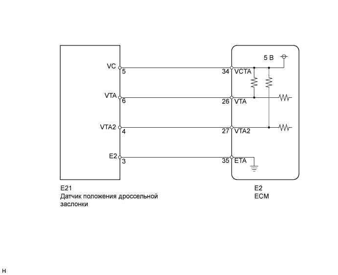
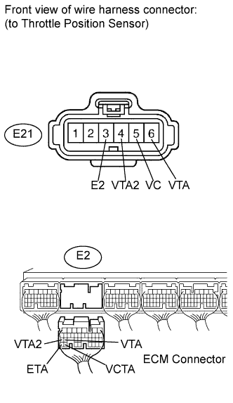
| 2.CHECK HARNESS AND CONNECTOR (THROTTLE POSITION SENSOR - ECM) |
 |
Disconnect the E21 throttle body connector.
Disconnect the E2 ECM connector.
Measure the resistance according to the value(s) in the table below.
| Tester Connection | Condition | Specified Condition |
| E21-5 (VC) - E2-34 (VCTA) | Always | Below 1 Ω |
| E21-6 (VTA) - E2-26 (VTA1) | Always | Below 1 Ω |
| E21-4 (VTA2) - E2-27 (VTA2) | Always | Below 1 Ω |
| E21-3 (E2) - E2-35 (ETA) | Always | Below 1 Ω |
| Tester Connection | Condition | Specified Condition |
| E21-5 (VC) or E2-34 (VCTA)- Body ground | Always | 10 kΩ or higher |
| E21-6 (VTA) or E2-26 (VTA1) - Body ground | Always | 10 kΩ or higher |
| E21-4 (VTA2) or E2-27 (VTA2) - Body ground | Always | 10 kΩ or higher |
|
| ||||
| OK | |
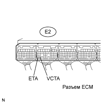
| 3.INSPECT ECM (VCTA VOLTAGE) |
 |
Disconnect the E21 throttle body connector.
Turn the engine switch on (IG).
Measure the voltage according to the value(s) in the table below.
| Tester Connection | Switch Condition | Specified Condition |
| E2-34 (VCTA) - E2-35 (ETA) | Engine switch on (IG) | 4.5 to 5.0 V |
|
| ||||
| OK | |
| 4.REPLACE THROTTLE BODY |
Replace the throttle body (see page Нажмите здесь).
| NEXT | |
| 5.CHECK WHETHER DTC OUTPUT RECURS (THROTTLE POSITION SENSOR DTCS) |
Connect the intelligent tester to the DLC3.
Turn the engine switch on (IG) and turn the tester ON.
Clear DTCs (see page Нажмите здесь).
Start the engine.
Allow the engine to idle for 15 seconds or more.
Enter the following menus: Powertrain / Engine / DTC.
Read DTCs.
| Display (DTC Output) | Proceed to |
| P0120, P0122, P0123, P0220, P0223, and/or P2135 | A |
| No output | B |
|
| ||||
| A | ||
| ||
