DTC P2102 Throttle Actuator Control Motor Circuit Low |
DTC P2103 Throttle Actuator Control Motor Circuit High |
| DTC No. | DTC Detection Condition | Trouble Area |
| P2102 | Conditions (a) and (b) continue for 2.0 seconds (1 trip detection logic): (a) Throttle actuator duty ratio 80% or more (b) Throttle actuator current 0.5 A or less |
|
| P2103 | Either of following conditions is met (1 trip detection logic):
|
|
| 1.INSPECT THROTTLE BODY (RESISTANCE OF THROTTLE ACTUATOR) |
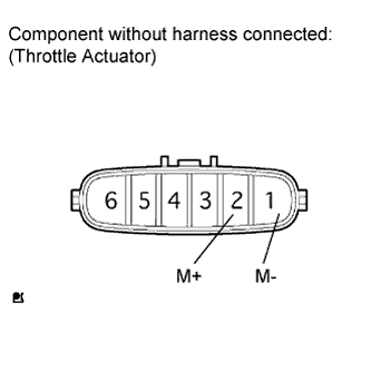 |
Disconnect the E21 throttle body connector.
Measure the resistance according to the value(s) in the table below.
| Tester Connection | Condition | Specified Condition |
| 2 (M+) - 1 (M-) | 20°C (68°F) | 0.3 to 100 Ω |
|
| ||||
| OK | |
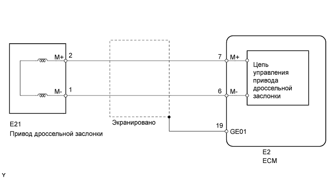
| 2.CHECK HARNESS AND CONNECTOR (THROTTLE ACTUATOR - ECM) |
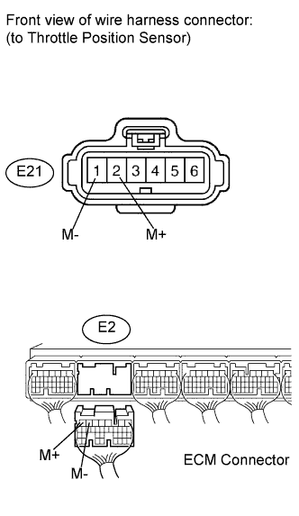 |
Disconnect the E21 throttle body connector.
Disconnect the E2 ECM connector.
Measure the resistance according to the value(s) in the table below.
| Tester Connection | Condition | Specified Condition |
| E21-2 (M+) - E2-7 (M+) | Always | Below 1 Ω |
| E21-1 (M-) - E2-6 (M-) | Always | Below 1 Ω |
| Tester Connection | Condition | Specified Condition |
| E21-2 (M+) or E2-7 (M+) - Body ground | Always | 10 kΩ or higher |
| E21-1 (M-) or E2-6 (M-) - Body ground | Always | 10 kΩ or higher |
|
| ||||
| OK | |
| 3.INSPECT THROTTLE BODY (VISUALLY CHECK THROTTLE VALVE) |
Check for foreign objects between the throttle valve and the housing.
|
| ||||
| OK | |
| 4.INSPECT THROTTLE VALVE |
Check if the throttle valve opens and closes smoothly.
|
| ||||
| OK | ||
| ||
