DTC P2118 Throttle Actuator Control Motor Current Range / Performance |
| DTC No. | DTC Detection Condition | Trouble Area |
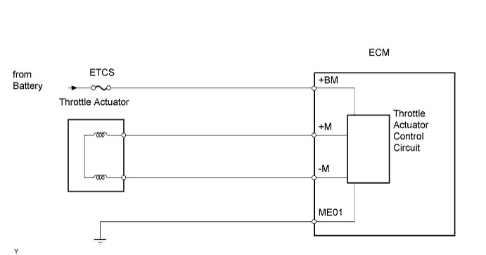
| P2118 | Open in ETCS power source (+BM) circuit (1 trip detection logic) |
|
| 1.CHECK FUSE (ETCS FUSE) |
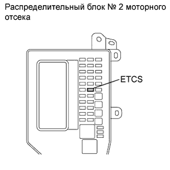 |
Remove the ETCS fuse from the engine room No. 2 junction block.
Measure the resistance of the fuse.
| Tester Connection | Condition | Specified Condition |
| ETCS fuse | Always | Below 1 Ω |
|
| ||||
| OK | |
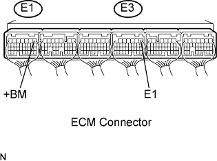
| 2.INSPECT ECM (+BM VOLTAGE) |
 |
Measure the voltage according to the value(s) in the table below.
| Tester Connection | Switch Condition | Specified Condition |
| E1-1 (+BM) - E3-1 (E1) | Engine switch on (IG) | 11 to 14 V |
|
| ||||
| NG | |
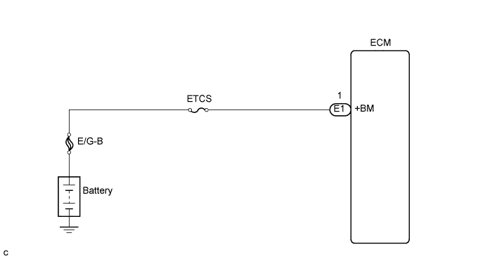
| 3.CHECK HARNESS AND CONNECTOR (ECM - ETCS FUSE, ETCS FUSE - BATTERY) |
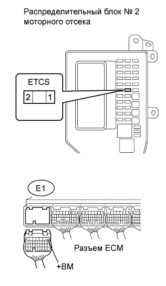 |
Check the harness and connector between the ETCS fuse and ECM.
Remove the ETCS fuse from the engine room No. 2 junction block.
Disconnect the E1 ECM connector.
Measure the resistance according to the value(s) in the table below.
| Tester Connection | Condition | Specified Condition |
| ETCS fuse (2) - E1-1 (+BM) | Always | Below 1 Ω |
| Tester Connection | Condition | Specified Condition |
| ETCS fuse (2) or E1-1 (+BM) - Body ground | Always | 10 kΩ or higher |
Check the harness and connector between the ETCS fuse and positive battery cable.
Remove the ETCS fuse from the engine room No. 2 junction block.
Disconnect the positive battery cable.
Measure the resistance according to the value(s) in the table below.
| Tester Connection | Condition | Specified Condition |
| Positive battery cable - ETCS fuse (1) | Always | Below 1 Ω |
| Tester Connection | Condition | Specified Condition |
| Positive battery cable or ETCS fuse (1) - Body ground | Always | 10 kΩ or higher |
|
| ||||
| OK | ||
| ||
