DTC P2121 Throttle / Pedal Position Sensor / Switch "D" Circuit Range / Performance |
| DTC No. | DTC Detection Condition | Trouble Area |
| P2121 | Difference between VPA and VPA2 less than 0.4 V, or more than 1.2 V for 0.5 seconds (1 trip detection logic) |
|
| 1.READ VALUE OF INTELLIGENT TESTER (ACCELERATOR POSITION NO. 1 AND ACCELERATOR POSITION NO. 2) |
 |
Connect the intelligent tester to the DLC3.
Turn the engine switch on (IG) and turn the tester ON.
Enter the following menus: Power train / Engine / Data List / Accelerator Position No. 1 and Accelerator Position No. 2.
Read the values displayed on the tester.
| Accelerator Pedal Operation | Accelerator Position No. 1 (AP#1) | Accelerator Position No. 2 (AP#2) |
| Released | 0.5 to 1.1 V | 1.2 to 2.0 V |
| Depressed | 2.6 to 4.5 V | 3.4 to 5.0 V |
|
| ||||
| NG | |
| 2.CHECK HARNESS AND CONNECTOR (ACCELERATOR PEDAL POSITION SENSOR - ECM) |
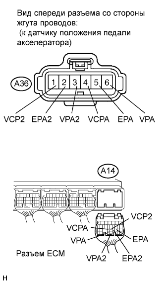 |
Disconnect the A36 Accelerator Pedal Position (APP) sensor connector.
Disconnect the A14 ECM connector.
Measure the resistance according to the value(s) in the table below.
| Tester Connection | Condition | Specified Condition |
| A36-6 (VPA) - A14-29 (VPA) | Always | Below 1 Ω |
| A36-5 (EPA) - A14-20 (EPA) | Always | Below 1 Ω |
| A36-4 (VCPA) - A14-23 (VCPA) | Always | Below 1 Ω |
| A36-3 (VPA2) - A14-28 (VPA2) | Always | Below 1 Ω |
| A36-2 (EPA2) - A14-21 (EPA2) | Always | Below 1 Ω |
| A36-1 (VCP2) - A14-22 (VCP2) | Always | Below 1 Ω |
| Tester Connection | Condition | Specified Condition |
| A36-6 (VPA) or A14-29 (VPA) - body ground | Always | 10 kΩ or higher |
| A36-5 (EPA) or A14-20 (EPA) - body ground | Always | 10 kΩ or higher |
| A36-4 (VCPA) or A14-23 (VCPA) - body ground | Always | 10 kΩ or higher |
| A36-3 (VPA2) or A14-28 (VPA2) - body ground | Always | 10 kΩ or higher |
| A36-2 (EPA2) or A14-21 (EPA2) - body ground | Always | 10 kΩ or higher |
| A36-1 (VCP2) or A14-22 (VCP2) - body ground | Always | 10 kΩ or higher |
|
| ||||
| OK | |
| 3.REPLACE ACCELERATOR PEDAL ROD ASSEMBLY |
Replace the accelerator pedal rod assembly (see page Нажмите здесь).
| NEXT | |
| 4.CHECK WHETHER DTC OUTPUT RECURS (ACCELERATOR PEDAL POSITION SENSOR DTCS) |
Connect the intelligent tester to the DLC3.
Turn the engine switch on (IG) and turn the tester ON.
Clear DTCs (see page Нажмите здесь).
Start the engine.
Allow the engine to idle for 15 seconds.
Enter the following menus: Powertrain / Engine / DTC.
Read DTCs.
| Display (DTC Output) | Proceed to |
| P2121 | A |
| No output | B |
|
| ||||
| A | ||
| ||
