ТОПЛИВНЫЙ БАК > УСТАНОВКА |
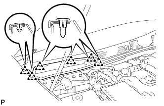
| 1. INSTALL FUEL TANK CUSHION |
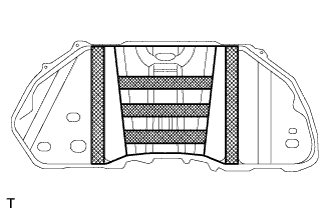 |
Install the 5 tank cushions and fuel tank protector.
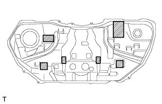 |
Install the 6 tank cushions.
| 2. INSTALL FUEL TANK PROTECTOR NO.2 |
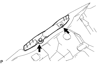 |
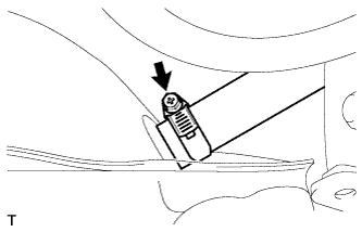
Install the clamp to the fuel tank.
Install the bolt and clip and fuel tank protector to the fuel tank.
| 3. INSTALL FUEL TANK MAIN TUBE SUB-ASSEMBLY |
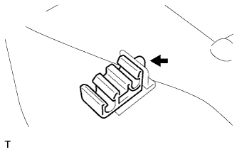 |
Install the fuel hose clamp.
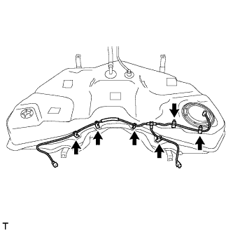 |
Install the fuel tank main tube to the fuel tank with the 6 clamps.
| 4. INSTALL FUEL SENDER GAUGE ASSEMBLY |
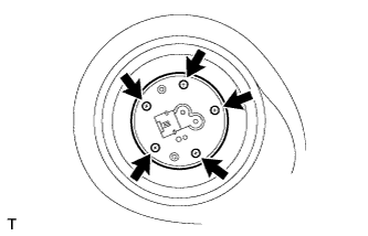 |
Install a new gasket and sender gauge to the fuel tank with the 5 screws.
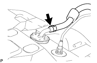
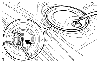
| 5. INSTALL FUEL SUCTION WITH PUMP AND GAUGE TUBE ASSEMBLY |
Apply a light coat of gasoline to a new gasket, and install it to the fuel tank.
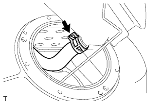 |
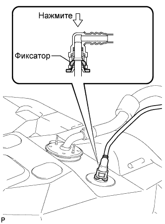
Connect the fuel hose, and set the fuel suction with pump and gauge.
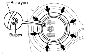 |
Install the set plate with the 8 bolts.
| 6. INSTALL FUEL TANK SUB-ASSEMBLY |
Set the fuel tank on a mission jack.
Raise the mission jack so that the fuel tank breather tube can be connected.
 |
Connect the fuel tank breather tube sub-assembly NO. 1.
 |
Connect the fuel tank to canister tube sub-assembly.
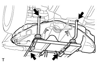 |
Slowly raise the mission jack, and install the 2 fuel tank bands with the 4 bolts.
 |
Connect the filler pipe hose to the fuel tank.
Tighten the clamp.
 |
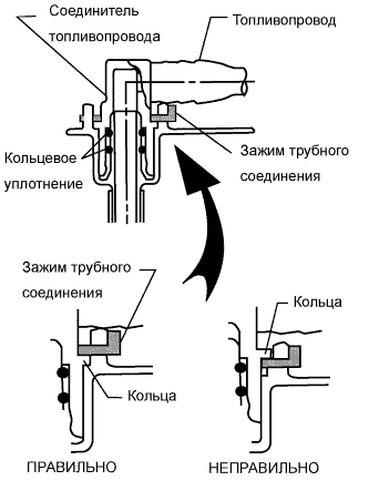
Connect the fuel main tube.
|
Connect the fuel return tube.
| 7. INSTALL PROPELLER WITH CENTER BEARING SHAFT ASSEMBLY |
Install the propeller with center bearing shaft (see page Нажмите здесь).
| 8. INSTALL EXHAUST PIPE ASSEMBLY |
Install the exhaust pipe (see page Нажмите здесь).
| 9. INSTALL REAR FLOOR SERVICE HOLE COVER |
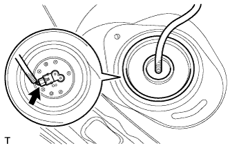 |
Connect the fuel sender gauge connector.
Install the service hole cover with new butyl tape.
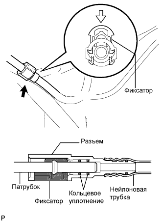
| 10. INSTALL FUEL TANK MAIN AND RETURN TUBE |
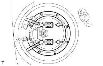 |
Install the fuel main tube and fuel return tube with the 2 tube joint clips.
| 11. INSTALL REAR FLOOR NO. 2 SERVICE HOLE COVER |
 |
Connect the connector.
Install the service hole cover with new butyl tape.
| 12. CONNECT CABLE TO NEGATIVE BATTERY TERMINAL |
| 13. INSTALL COWL TOP VENTILATOR LOUVER RH |
 |
Install the 6 clips and cowl top ventilator louver RH.
| 14. PERFORM INITIALIZATION |
Perform initialization (see page Нажмите здесь).
| 15. CHECK FOR FUEL LEAKS |
Connect the intelligent tester to the DLC3.
Turn the engine switch on (IG).
Push the intelligent tester main switch ON.
Select the following menus: Powertrain / Engine / Active Test / Control the Fuel Pump /Speed.
Check the fuel pump operation.
Check for pressure in the fuel inlet tube from the fuel line. Check that the sound of fuel flowing in the fuel tank can be heard.
If no sound can be heard, check the integration relay, fuel pump, ECM and wiring connector.
Check for fuel leaks.
Check that there are no fuel leaks anywhere on the system after performing maintenance.
If there is a fuel leak, repair or replace parts as necessary.
| 16. INSTALL REAR SEAT ASSEMBLY (for Power Seat) |
Install the rear seat assembly (see page Нажмите здесь).
| 17. INSTALL REAR SEAT ASSEMBLY (for Ottoman) |
Install the rear seat assembly (see page Нажмите здесь).
| 18. INSTALL REAR SEAT CUSHION ASSEMBLY (for Fixed Type) |
Install the rear seat cushion assembly (see page Нажмите здесь).
