КАТУШКА ЗАЖИГАНИЯ И СВЕЧА ЗАЖИГАНИЯ > УСТАНОВКА |
| 1. INSTALL SPARK PLUG |
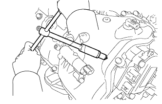 |
Using a 16 mm plug wrench, install the 8 spark plugs.
| 2. INSTALL IGNITION COIL ASSEMBLY |
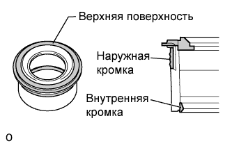 |
Perform a visual inspection on the spark plug tube gasket
| Inspection Area | Inspection Result |
| Upper surface | No scratches or deformation |
| Outer lip | No scratches or deformation |
| Inner lip | No scratches |
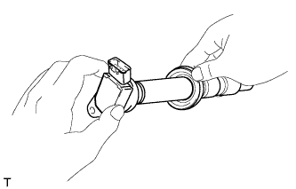 |
Set each spark plug tube gasket on each ignition coil.
 |
After installing each spark plug tube gasket, securely insert each ignition coil.
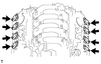 |
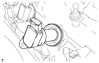
Install the 8 bolts.
Connect the 8 ignition coil connectors.
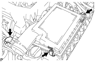
| 3. INSTALL AIR CLEANER ASSEMBLY RH |
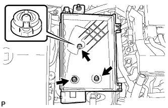 |
Install the air cleaner case with the 2 nuts and clip.
Install the air cleaner element to the air cleaner case.
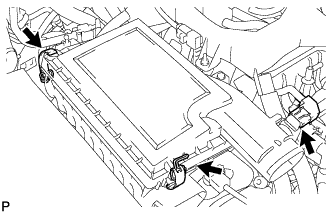 |
Install the air cleaner cap with the 2 clamps.
Connect the MAF meter connector.
| 4. INSTALL AIR CLEANER ASSEMBLY LH |
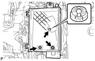 |
Install the air cleaner case with the 2 nuts and clip.
Install the air cleaner element to the air cleaner case.
 |
Install the air cleaner cap with the 2 clamps.
Connect the MAF meter connector.
| 5. INSTALL SKID CONTROL ECU BRACKET |
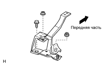 |
Установите кронштейн, закрепив его болтом и 2 гайками.
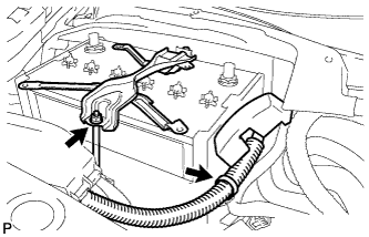
| 6. INSTALL SKID CONTROL ECU |
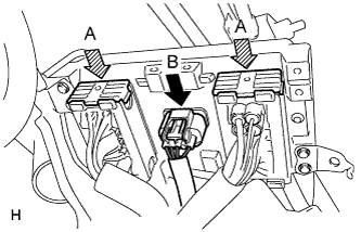 |
Подсоедините 2 разъема (A) и нажмите рычаги блокировки вниз, чтобы зафиксировать разъемы.
Подсоедините разъем (В).
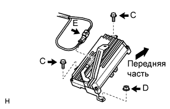 |
Установите ЭБУ и закрепите его 2 болтами (C) и гайкой (D).
Подсоедините короткозамыкатель имитатора хода педали тормоза (E) к кронштейну ЭБУ системы противоскольжения.
| 7. INSTALL BATTERY TRAY |
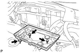 |
Install the battery tray with the 3 bolts.
| 8. INSTALL BATTERY |
Install the battery.
Install the battery insulator.
 |
Install the No. 2 battery clamp bolt and battery clamp with the nut.
Connect the battery cable clamp.
Connect the positive (+) battery cable to the battery terminal.
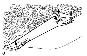
| 9. INSTALL NO. 1 AIR CLEANER INLET |
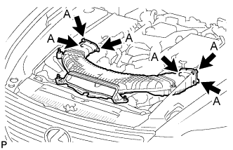 |
Align the holes with the connection areas labeled A, and attach the No. 1 air cleaner inlet.
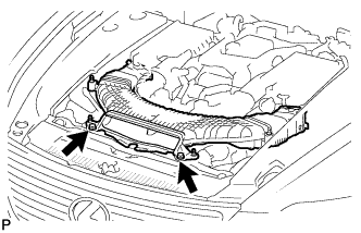 |
Install the No. 1 air cleaner inlet with the 2 bolts.
| 10. INSTALL ENGINE ROOM SIDE COVER RH |
 |
Install the side cover with the 4 clips.
| 11. INSTALL ENGINE ROOM SIDE COVER LH |
 |
Install the side cover with the 4 clips.
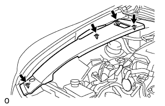
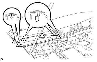
| 12. INSTALL AIR CLEANER INLET COVER |
 |
Attach the 4 clips B.
Install the air cleaner inlet cover with the 5 clips A.
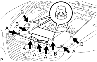
| 13. INSTALL V-BANK COVER SUB-ASSEMBLY |
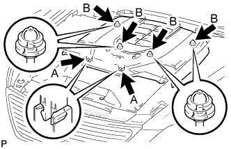 |
After sliding the cover from the vehicle front to the rear to attaching the 2 clips A, attach the 4 clips B and install the V bank cover.
| 14. CONNECT CABLE TO NEGATIVE BATTERY TERMINAL |
| 15. INSTALL COWL TOP VENTILATOR LOUVER RH |
 |
Install the 6 clips and cowl top ventilator louver RH.
| 16. PERFORM INITIALIZATION |
Perform initialization (see page Нажмите здесь).
