DTC P0327 Knock Sensor 1 Circuit Low Input (Bank 1 or Single Sensor) |
DTC P0328 Knock Sensor 1 Circuit High Input (Bank 1 or Single Sensor) |
DTC P032C Knock Sensor 3 Circuit Low |
DTC P032D Knock Sensor 3 Circuit High |
DTC P0332 Knock Sensor 2 Circuit Low Input (Bank 2) |
DTC P0333 Knock Sensor 2 Circuit High Input (Bank 2) |
DTC P033C Knock Sensor 4 Circuit Low Input |
DTC P033D Knock Sensor 4 Circuit High Input |
| DTC No. | DTC Detection Condition | Trouble Area |
| P0327 | Output voltage of knock sensor (bank 1 sensor 1) is 0.5 V or less (1 trip detection logic) |
|
| P0328 | Output voltage of knock sensor (bank 1 sensor 1) is 4.5 V or more (1 trip detection logic) |
|
| P0332 | Output voltage of knock sensor (bank 2 sensor 1) is 0.5 V or less (1 trip detection logic) |
|
| P0333 | Output voltage of knock sensor (bank 2 sensor 1) is 4.5 V or more (1 trip detection logic) |
|
| P032C | Output voltage of knock sensor (bank 1 sensor 2) is 0.5 V or less (1 trip detection logic) |
|
| P032D | Output voltage of knock sensor (bank 1 sensor 2) is 4.5 V or more (1 trip detection logic) |
|
| P033C | Output voltage of knock sensor (bank 2 sensor 2) is 0.5 V or less (1 trip detection logic) |
|
| P032D | Output voltage of knock sensor (bank 2 sensor 2) is 4.5 V or more (1 trip detection logic) |
|
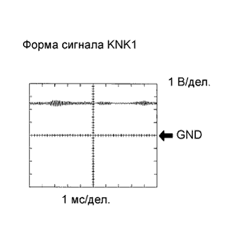
| Item | Content |
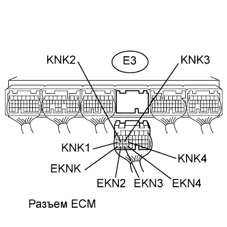
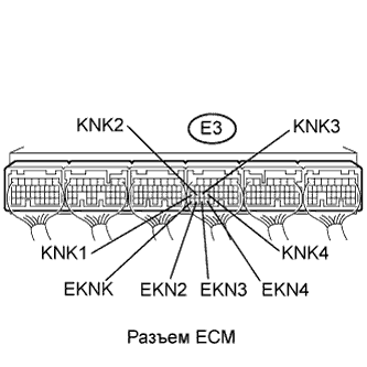
| Terminal | KNK1 - EKNK KNK2 - EKN2 KNK3 - EKN3 KNK4 - EKN4 |
| Equipment Setting | 0.01 to 10 V/DIV. 0.01 to 10 msec./DIV. |
| Condition | Keep engine speed at 4000 rpm with warm engine |
| 1.INSPECT KNOCK SENSOR |
 |
Disconnect the E3 ECM connector.
Measure the resistance according to the value(s) in the table below.
| Tester Connection | Condition | Specified Condition |
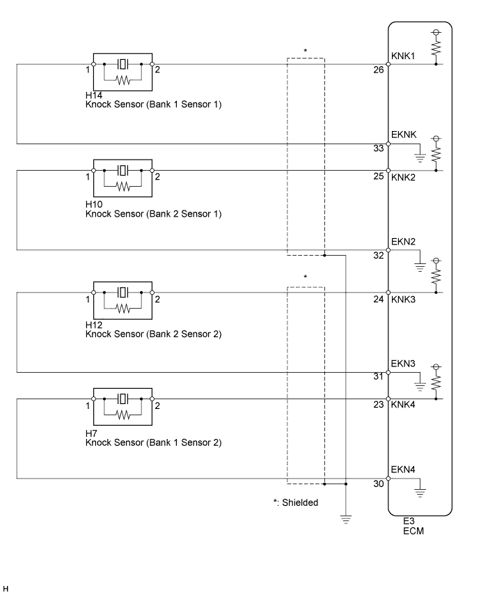
| E3-26 (KNK1) - E3-33 (EKNK) | 20°C | 120 to 280 kΩ |
| E3-25 (KNK2) - E3-32 (EKN2) | 20°C | 120 to 280 kΩ |
| E3-24 (KNK3) - E3-31 (EKN3) | 20°C | 120 to 280 kΩ |
| E3-23 (KNK4) - E3-30 (EKN4) | 20°C | 120 to 280 kΩ |
|
| ||||
| NG | |
| 2.CHECK HARNESS AND CONNECTOR (ECM - KNOCK SENSOR) |
 |
Disconnect the E3 ECM connector.
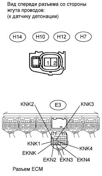
Disconnect the H14, H10, H12 or H7 knock sensor connector.
Measure the resistance according to the value(s) in the table below.
| Tester Connection | Condition | Specified Condition |
| E3-26 (KNK1) - H14-2 | Always | Below 1 Ω |
| E3-33 (EKNK) - H14-1 | Always | Below 1 Ω |
| E3-25 (KNK2) - H10-2 | Always | Below 1 Ω |
| E3-32 (EKN2) - H10-1 | Always | Below 1 Ω |
| E3-24 (KNK3) - H12-2 | Always | Below 1 Ω |
| E3-31 (EKN3) - H12-1 | Always | Below 1 Ω |
| E3-23 (KNK4) - H7-2 | Always | Below 1 Ω |
| E3-30 (EKN4) - H7-1 | Always | Below 1 Ω |
| Tester Connection | Condition | Specified Condition |
| E3-26 (KNK1) or H14-2 - Body ground | Always | 10 kΩ or higher |
| E3-33 (EKNK) or H14-1 - Body ground | Always | 10 kΩ or higher |
| E3-25 (KNK2) or H10-2 - Body ground | Always | 10 kΩ or higher |
| E3-32 (EKN2) or H10-1 - Body ground | Always | 10 kΩ or higher |
| E3-24 (KNK3) or H12-2 - Body ground | Always | 10 kΩ or higher |
| E3-31 (EKN3) or H12-1 - Body ground | Always | 10 kΩ or higher |
| E3-23 (KNK4) or H7-2 - Body ground | Always | 10 kΩ or higher |
| E3-30 (EKN4) or H7-1 - Body ground | Always | 10 kΩ or higher |
|
| ||||
| OK | ||
| ||
| 3.INSPECT ECM |
 |
Turn the engine switch on (IG).
Measure the voltage according to the value(s) in the table below.
| Tester Connection | Switch Condition | Specified Condition |
| E3-26 (KNK1) - E3-33 (EKNK) | Engine switch on (IG) | 4.5 to 5.5 V |
| E3-25 (KNK2) - E3-32 (EKN2) | Engine switch on (IG) | 4.5 to 5.5 V |
| E3-24 (KNK3) - E3-31 (EKN3) | Engine switch on (IG) | 4.5 to 5.5 V |
| E3-23 (KNK4) - E3-30 (EKN4) | Engine switch on (IG) | 4.5 to 5.5 V |
|
| ||||
| OK | ||
| ||
