DTC    P0617    Starter Relay Circuit High

для подготовки Нажмите здесь


DESCRIPTION

While the engine is being cranked, the positive battery voltage is applied to terminal STA of the ECM.
If the ECM detects the Starter Control (STA) signal while the vehicle is being driven, it determines that there is a malfunction in the STA circuit. The ECM then illuminates the MIL and sets the DTC.
This monitor runs when the vehicle is driven at 12.4 mph (20 km/h) for over 20 seconds.

DTC No.
DTC Detection Condition
Trouble Area
P0617
When conditions (a), (b) and (c) are met, positive (+B) battery voltage 10.5 V or more applied to ECM for 20 seconds
(1 trip detection logic):
(a) Vehicle speed more than 12.4 mph (20 km/h)
(b) Engine speed more than 1000 rpm
(c) STA signal ON
  1. Park/Neutral Position (PNP) switch
  2. Cranking holding function circuit
  3. ECM

WIRING DIAGRAM


A147867E03


INSPECTION PROCEDURE

УКАЗАНИЕ:
  1. The following troubleshooting flowchart is based on the premise that the engine is cranked normally. If the engine does not crank, proceed to the problem symptoms table (see page Нажмите здесь).
  2. Read freeze frame data using the intelligent tester. Freeze frame data records the engine condition when malfunctions are detected. When troubleshooting, freeze frame data can help determine if the vehicle was moving or stationary, if the engine was warmed up or not, if the air-fuel ratio was lean or rich, and other data from the time the malfunction occurred.

1.READ VALUE OF INTELLIGENT TESTER (STARTER SIGNAL)
  1. Connect the intelligent tester to the DLC3.

  1. Turn the engine switch on (IG) and turn the tester ON.

  1. Enter the following menus: Powertrain / Engine / Data List / Starter Signal.

  1. Check the value displayed on the tester when the engine switch is turned on (IG) and the engine is started.

    OK:

    Engine Switch Condition
    on (IG)
    ENGINE START
    Starter Signal
    OFF
    ON


OK
REPLACE ECM (Нажмите здесь)
NG


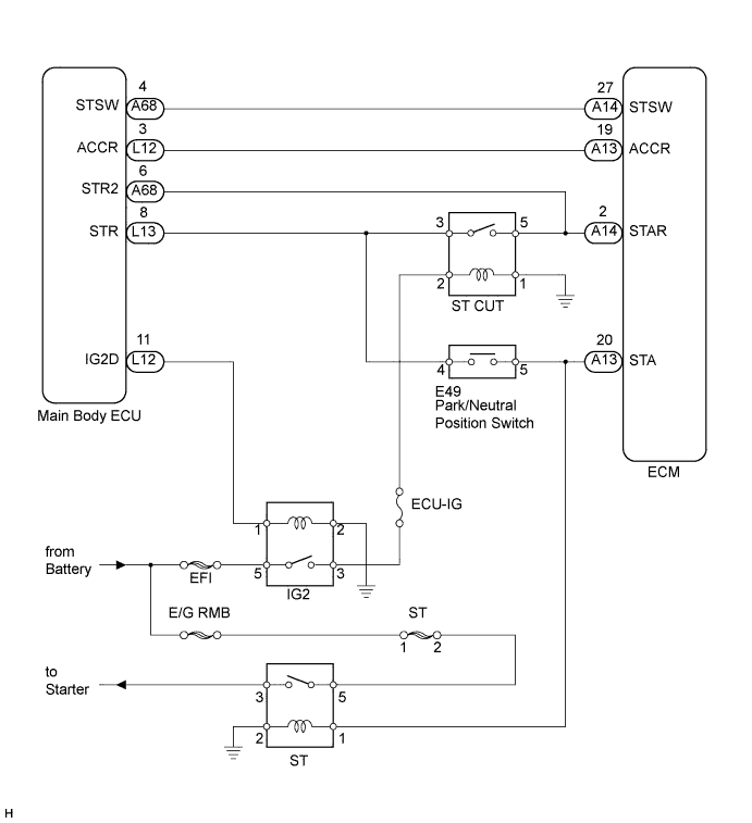
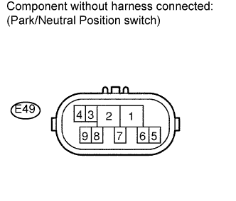
2.INSPECT PARK / NEUTRAL POSITION SWITCH ASSEMBLY


    C110340E71
  1. Inspect the Park/Neutral Position (PNP) switch.

    1. Disconnect the E49 switch connector.

    2. Measure the resistance according to the value(s) in the table below.

      Standard resistance:
      Tester Connection
      Gear Selector Lever Position
      Specified Condition
      4 - 5
      P
      Below 1 Ω
      4 - 5
      N
      Below 1 Ω


NG
REPLACE PARK / NEUTRAL POSITION SWITCH (THEN CHECK CRANKING HOLDING FUNCTION CIRCUIT) (Нажмите здесь)
OK

CHECK CRANKING HOLDING FUNCTION CIRCUIT (Нажмите здесь)