DTC P0335 Crankshaft Position Sensor "A" Circuit |
DTC P0337 Crankshaft Position Sensor "A" Circuit Low Input |
DTC P0338 Crankshaft Position Sensor "A" Circuit High Input |
DTC P0339 Crankshaft Position Sensor "A" Circuit Intermittent |
| DTC No. | DTC Detection Condition | Trouble Area |
| P0335 | When either condition below is met:
|
|
| P0337 | Output voltage of CKP sensor 0.3 V or less for 4 seconds (1 trip detection logic) |
|
| P0338 | Output voltage of CKP sensor 4.7 V or more for 4 seconds (1 trip detection logic) |
|
| P0339 | Under conditions (a), (b) and (c), no CKP sensor signal to ECM for 0.05 seconds or more (1 trip detection logic): (a) Engine speed 1000 rpm or more (b) Starter signal OFF (c) 3 seconds or more have lapsed since starter signal switched from ON to OFF |
|
 |
| Item | Content |
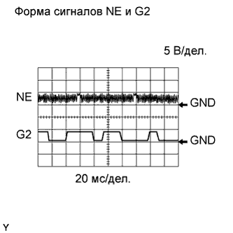
| Terminal | NE+ - NE- G2+ - G2- |
| Equipment Setting | 5 V/DIV., 20 msec./DIV. |
| Condition | Cranking or idling |
| 1.READ VALUE OF INTELLIGENT TESTER (ENGINE SPEED) |
Connect the intelligent tester to the DLC3.
Turn the engine switch on (IG) and turn the tester ON.
Enter the following menus: Powertrain / Engine / Data List / Engine Speed.
Start the engine.
Read the values displayed on the tester while the engine is running.
|
| ||||
| NG | |
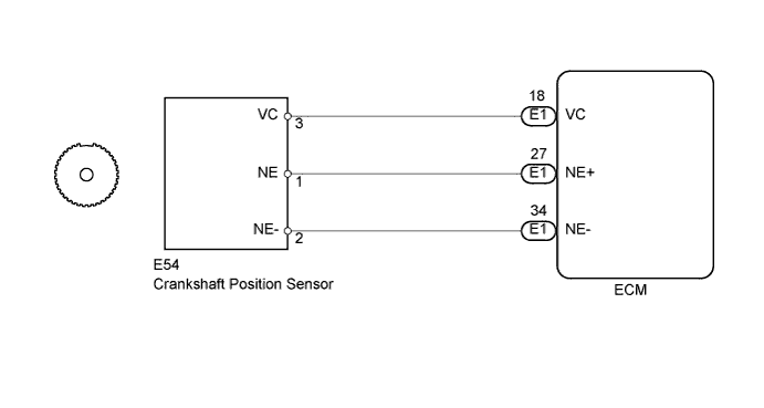
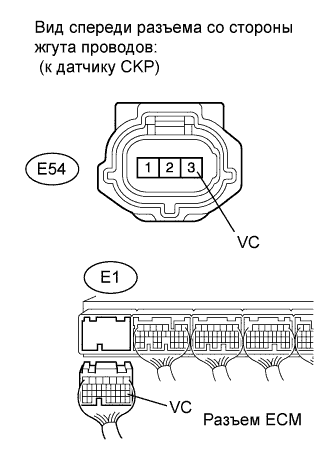
| 2.INSPECT CRANKSHAFT POSITION SENSOR (SENSOR POWER SOURCE) |
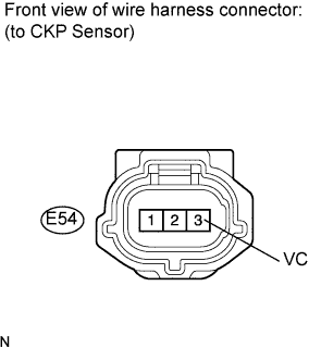 |
Disconnect the E54 crankshaft position sensor connector.
Measure the voltage according to the value(s) in the table below.
| Tester Connection | Switch Condition | Specified Condition |
| E54--3 (VC) - Body ground | Engine switch on (IG) | 4.5 to 5.0 V |
|
| ||||
| OK | |
| 3.CHECK HARNESS AND CONNECTOR (CRANKSHAFT POSITION SENSOR - ECM) |
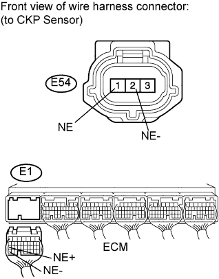 |
Disconnect the E54 crankshaft position sensor connector.
Disconnect the E1 ECM connector.
Measure the resistance according to the value(s) in the table below.
| Tester Connection | Condition | Specified Condition |
| E54-1 (NE) - E1-27 (NE+) | Always | Below 1 Ω |
| E54-2 (NE-) - E1-34 (NE-) | Always | Below 1 Ω |
| Tester Connection | Condition | Specified Condition |
| E54-1 (NE) or E1-27 (NE+) - Body ground | Always | 10 kΩ or higher |
| E54-2 (NE-) or E1-34 (NE-) - Body ground | Always | 10 kΩ or higher |
|
| ||||
| OK | |
| 4.CHECK SENSOR INSTALLATION (CRANKSHAFT POSITION SENSOR) |
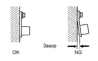 |
Check the crankshaft position sensor installation.
|
| ||||
| OK | |
| 5.CHECK CRANKSHAFT ANGLE SENSOR ROTOR (TEETH OF SENSOR ROTOR) |
Check the teeth of the sensor plate.
|
| ||||
| OK | |
| 6.REPLACE CRANKSHAFT POSITION SENSOR |
Replace the crankshaft position sensor (see page Нажмите здесь).
| NEXT | |
| 7.CHECK WHETHER DTC OUTPUT RECURS (P0335, P0337, P0338 AND/OR P0339) |
Connect the intelligent tester to the DLC3.
Turn the engine switch on (IG).
Turn the tester ON.
Clear DTCs
Start the engine.
Enter the following menus: Powertrain / Engine / DTC / Pending Codes.
Read DTCs.
| Display (DTC Output) | Proceed to |
| No output | A |
| P0335, P0337, P0338 and/or P0339 | B |
|
| ||||
| A | ||
| ||
| 8.CHECK HARNESS AND CONNECTOR (CRANKSHAFT POSITION SENSOR - ECM) |
 |
Disconnect the E54 crankshaft position sensor connector.
Disconnect the E1 ECM connector.
Measure the resistance according to the value(s) in the table below.
| Tester Connection | Condition | Specified Condition |
| E54-3 (VC) - E1-18 (VC) | Always | Below 1 Ω |
| Tester Connection | Condition | Specified Condition |
| E54-3 (VC) or E1-18 (VC) - Body ground | Always | 10 kΩ or higher |
|
| ||||
| OK | ||
| ||
