DTC P0136 Oxygen Sensor Circuit Malfunction (Bank 1 Sensor 2) |
DTC P0156 Oxygen Sensor Circuit Malfunction (Bank 2 Sensor 2) |
| DTC No. | DTC Detection Condition | Trouble Area |
| P0136 P0156 | Either of following conditions (a) or (b) is met : (a) HO2 sensor voltage remains below 0.4 V (lean) or above 0.5 V (rich) while vehicle is repeatedly accelerated and decelerated for 4 minutes or more (b) HO2 sensor voltage remains below 0.05 V for a long time period |
|
| Case | Front HO2 Sensor (Sensor 1) Output Voltage | Rear HO2 Sensor (Sensor 2) Output Voltage | Main Suspected Trouble Area |
| 1 |  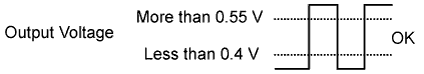 |  | - |
| 2 |  | |
|
| 3 | | |
|
| 4 | | |
|
| 1.CHECK OTHER DTC OUTPUT (IN ADDITION TO DTC P0136, P0156) |
Connect the intelligent tester to the DLC3.
Turn the engine switch on (IG) and turn the tester ON.
Enter the following menus: Powertrain / Engine / DTC.
Read the DTCs.
| Display (DTC output) | Proceed to |
| P0136 or P0156 | A |
| P0136 or P0156 and other DTCs | B |
|
| ||||
| A | |
| 2.READ DATA LIST (HEATED OXYGEN SENSOR (SENSOR 2) VOLTAGE) |
Connect the intelligent tester to the DLC3.
Enter the following menus: Powertrain / Engine / Data List / Primary / O2S B1 S2 (or O2S B2 S2).
Allow the engine to run at 2500 rpm for 3 minutes.
Depress the accelerator pedal quickly until the engine rpm reaches 4000 rpm 3 times.
|
| ||||
| NG | |
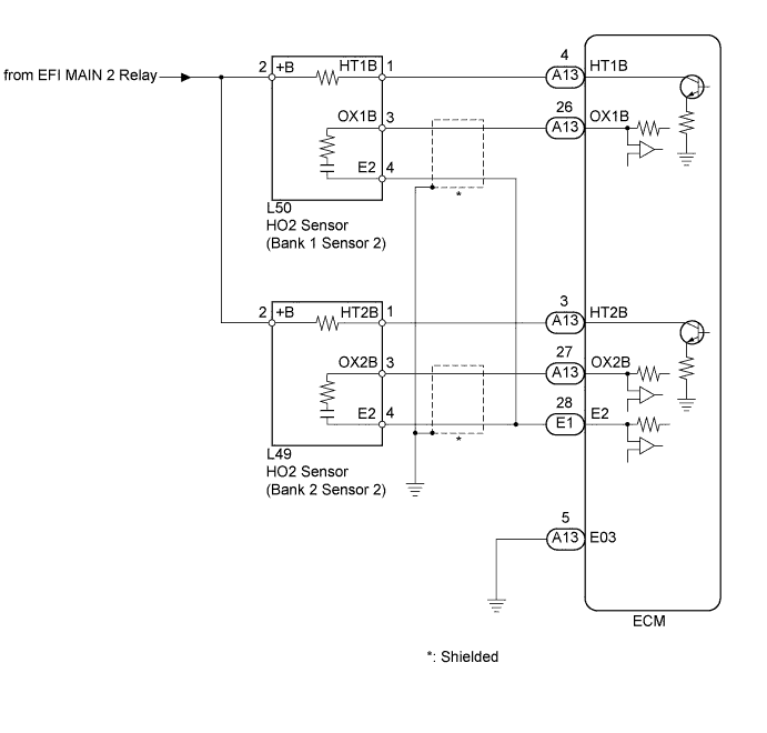
| 3.INSPECT HEATED OXYGEN SENSOR (HEATER RESISTANCE) |
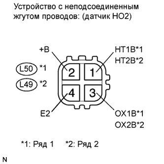 |
Disconnect the L49 and L50 sensor connectors.
Measure the resistance according to the value(s) in the table below.
| Tester Connection | Condition | Specified Condition |
| 1 (HT1B) - 2 (+B) | Always | 11 to 16 Ω |
| 1 (HT2B) - 2 (+B) | Always | 11 to 16 Ω |
| 1 (HT1B) - 4 (E2) | Always | 10 kΩ or higher |
| 1 (HT2B) - 4 (E2) | Always | 10 kΩ or higher |
|
| ||||
| OK | |
| 4.INSPECT EFI MAIN 2 RELAY |
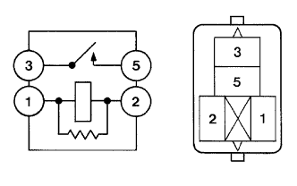 |
Remove the relay from the engine room No. 2 junction block.
Measure the resistance according to the value(s) in the table below.
| Terminal Connections | Condition | Specified Condition |
| 3 - 5 | When no battery voltage is applied to terminals 1 and 2 | 10 kΩ or higher |
| When battery voltage is applied to terminals 1 and 2 | Below 1 Ω |
|
| ||||
| OK | |
| 5.CHECK HARNESS AND CONNECTOR (HEATED OXYGEN SENSOR (SENSOR 2) - ECM) |
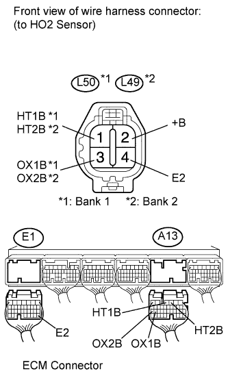 |
Disconnect the L49 and L50 sensor connectors.
Disconnect the A13 and E1 ECM connectors.
Measure the resistance according to the value(s) in the table below.
| Tester Connection | Condition | Specified Condition |
| L50-1 (HT1B) - A13-4 (HT1B) | Always | Below 1 Ω |
| L49-1 (HT2B) - A13-3 (HT2B) | Always | Below 1 Ω |
| L50-3 (OX1B) - A13-26 (OX1B) | Always | Below 1 Ω |
| L49-3 (OX2B) - A13-27 (OX2B) | Always | Below 1 Ω |
| L50-4 (E2) - E1-28 (E2) | Always | Below 1 Ω |
| L49-4 (E2) - E1-28 (E2) | Always | Below 1 Ω |
| L50-1 (HT1B) or A13-4 (HT1B) - Body ground | Always | 10 kΩ or higher |
| L49-1 (HT2B) or A13-3 (HT2B) - Body ground | Always | 10 kΩ or higher |
| L50-3 (OX1B) or A13-26 (OX1B) - Body ground | Always | 10 kΩ or higher |
| L49-3 (OX2B) or A13-27 (OX2B) - Body ground | Always | 10 kΩ or higher |
|
| ||||
| OK | ||
| ||
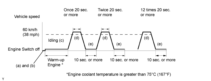
| 6.PERFORM CONFIRMATION DRIVING PATTERN |
| NEXT | |
| 7.READ OUTPUT DTC (DTC P0136 OR P0156 IS OUTPUT AGAIN) |
Connect the intelligent tester to the DLC3.
Turn the engine switch on (IG).
Turn the tester ON.
Start the engine and allow the engine to idle for 15 seconds or more.
Enter the following menus: Powertrain / Engine / DTC / Pending Codes.
Read the DTC.
| Display (DTC output) | Proceed to |
| P0136 or P0156 | A |
| No output | B |
|
| ||||
| A | ||
| ||
