DTC    P0420    Catalyst System Efficiency Below Threshold (Bank 1)

DTC    P0430    Catalyst System Efficiency Below Threshold (Bank 2)

для подготовки Нажмите здесь


MONITOR DESCRIPTION

The ECM uses heated oxygen sensors mounted before and after the Three-Way Catalyst (TWC) to monitor its efficiency. The front sensor sends pre-catalyst air-fuel information to the ECM. The rear sensor sends post-catalyst information to the ECM. The ECM compares these 2 signals to judge the efficiency of the catalyst and the catalyst's ability to store oxygen. During normal operation, the TWC stores and releases oxygen as needed. The capacity to store oxygen results in a low variation in the post-TWC exhaust stream as shown below.
If the catalyst is functioning normally, the waveform of the heated oxygen sensor (sensor 2) slowly switches between RICH and LEAN. If the catalyst is deteriorated, the waveform will alternate frequently between RICH and LEAN.
As the catalyst efficiency degrades, its ability to store oxygen is reduced and the catalyst output becomes more variable.
When running the catalyst monitor, the ECM begins to measure the signal length of the heated oxygen sensor (sensor 1) and heated oxygen sensor (sensor 2). The ECM calculates the rate of the signal length of the heated oxygen sensor (sensor 1) and heated oxygen sensor (sensor 2) (catalyst deterioration level). If the catalyst deterioration level exceeds the threshold, the ECM interprets this as a catalyst malfunction. The ECM illuminates the MIL (2 trip detection logic) and sets a DTC.
The monitor runs after:
  1. The engine is warmed up (Engine Coolant Temperature (ECT) is 75°C (167°F) or more).
  2. The vehicle is driven at approximately 60 to 100 km/h (37 to 63 mph) for 15 minutes.

A083860E06


A082718E04


DTC No.
DTC Detection Condition
Trouble Area
P0420
P0430
  1. After engine and TWC warmed up, and while vehicle is driven within set value and engine RPM ranges
  2. Waveforms of heated oxygen sensor (sensor 2) alternates frequency between RICH and LEAN (2 trip detection logic)
  1. Heated oxygen sensor (sensor 1)
  2. Heated oxygen sensor (sensor 2)
  3. Gas leakage in exhaust system
  4. TWC

CONFIRMATION DRIVING PATTERN


A054279E06

  1. Connect the intelligent tester to the DLC3.
  2. Start the engine and warm it up with all the accessories switched OFF until the ECT becomes stable.
  3. Run the engine at 2500 to 3000 rpm for about 3 minutes.

    УКАЗАНИЕ:
    Control the engine RPM so that the calculated catalyst temperature can be between 450 and 850°C (1022 and 1472°F). The calculated catalyst temperatures of bank 1 and bank 2 can be read by viewing Catalyst Temp (B1 S1) and Catalyst Temp (B2 S1) of the Data List.


  4. A093282E13
    Confirm that heated oxygen sensor [bank 1 sensor 1 (OX1A) and bank 2 sensor 1 (OX2A)] have waveforms that are around 0.5 V during feedback to the ECM. Then check the waveform of the heated oxygen sensor [bank 1 sensor 2 (OX1B) and bank 2 sensor 2 (OX2B)] for the same waveforms (0.5 V during feedback).

    УКАЗАНИЕ:
    If there is a malfunction in the catalyst, the waveform of the heated oxygen sensor (sensor 2) (OX1B, OX2B) is almost the same as that of the heated oxygen sensor (sensor 1) (OX1A, OX2A), which is shown.


WIRING DIAGRAM

Refer to DTC P0130 (see page Нажмите здесь).
Refer to DTC P0136 (see page Нажмите здесь).

INSPECTION PROCEDURE

УКАЗАНИЕ:
  1. Read freeze frame data using the intelligent tester. Freeze frame data records the engine conditions when a malfunction is detected. When troubleshooting, freeze frame data can help determine if the vehicle was running or stopped, if the engine was warmed up or not, if the air-fuel ratio was LEAN or RICH, and other data from the time the malfunction occurred.
  2. If DTC P0420 is displayed, check the bank 1 catalyst.
  3. If DTC P0430 is displayed, check the bank 2 catalyst.
  4. Bank 1 includes cylinder No. 1, but bank 2 does not. Cylinder No. 1 is located in the front part of the engine, opposite the transmission.

1.CHECK ANY OTHER DTCS OUTPUT (IN ADDITION TO DTC P0420, P0430)
  1. Connect the intelligent tester to the DLC3.

  1. Turn the engine switch on (IG) and turn the tester ON.

  1. Enter the following menus: Powertrain / Engine / DTC.

  1. Read the DTCs.

    Result:

    Display (DTC output)
    Proceed to
    P0420 or P0430
    A
    P0420 or P0430 and other DTCs
    B


B
GO TO DTC CHART (Нажмите здесь)
A


2.PERFORM ACTIVE TEST BY INTELLIGENT TESTER (CONTROL THE INJECTION VOLUME FOR A/F SENSOR)
  1. Connect the intelligent tester to the DLC3.

  1. Turn the engine switch on (IG) and turn the tester ON.

  1. Start the engine.

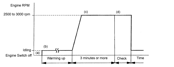
  1. Warm up the engine at an engine speed of 2500 rpm for approximately 90 seconds.

  1. Enter the following menus: Powertrain / Engine / Active Test / Control the Injection Volume for A/F Sensor.

  1. Perform the "Control the Injection Volume for A/F Sensor" operation with the engine in an idling condition (press the RIGHT or LEFT button to change the fuel injection volume).

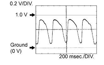
  1. Monitor the voltage outputs of the HO2 sensor (O2S B1 S1, O2S B2 S1, O2S B1 S2 and O2S B2 S2) displayed on the tester.

    УКАЗАНИЕ:
    1. The "Control the Injection Volume for A/F sensor" operation lowers the fuel injection volume by 12.5% or increases the injection volume by 24.8%.
    2. Each sensor reacts in accordance with increases and decreases in the fuel injection volume.


    Standard:

    Tester Display (Sensor)
    Injection Volume
    Status
    Voltage
    O2S B1 S1 or O2S B2 S1
    (Front HO2 Sensor)
    +24.8%
    Rich
    More than 0.55
    O2S B1 S1 or O2S B2 S1
    (Front HO2 Sensor)
    -12.5%
    Lean
    Less than 0.4
    O2S B1 S2 or O2S B2 S2
    (Rear HO2 Sensor)
    +24.8%
    Rich
    More than 0.5
    O2S B1 S2 or O2S B2 S2
    (Rear HO2 Sensor)
    -12.5%
    Lean
    Less than 0.4


    Result:

    Status
    O2S B1 S1 or O2S B2 S1
    Status
    O2S B1 S2 or O2S B2 S2
    A/F Condition and HO2 Sensors (sensors 1 and 2) Condition
    Misfire
    Main Suspected Trouble Area
    Proceed to
    Lean / Rich
    Lean / Rich
    Normal
    -
    1. TWC
    2. Gas leakage from exhaust system
    A
    Lean
    Lean / Rich
    HO2 sensor (sensor 1) malfunction
    -
    HO2 sensor (sensor 1)
    B
    Rich
    Lean / Rich
    HO2 sensor (sensor 1) malfunction
    -
    HO2 sensor (sensor 1)
    B
    Lean / Rich
    Lean
    HO2 sensor (sensor 2) malfunction
    -
    1. HO2 sensor (sensor 2)
    2. Gas leakage from exhaust system
    C
    Lean / Rich
    Rich
    HO2 sensor (sensor 2) malfunction
    -
    1. HO2 sensor (sensor 2)
    2. Gas leakage from exhaust system
    C
    Lean
    Lean
    Actual air-fuel ratio (A/F) lean
    May occur
    1. Extremely rich or lean actual A/F
    2. Gas leakage from exhaust system
    A
    Rich
    Rich
    Actual A/F rich
    -
    1. Extremely rich or lean actual A/F
    2. Gas leakage from exhaust system
    A

    Lean: During "Control the Injection Volume for A/F sensor", the HO2 sensor (sensor 1 and 2) output voltages are consistently less than 0.4 V.
    Rich: During "Control the Injection Volume for A/F sensor", the HO2 sensor (sensor 1 and 2) output voltages are consistently more than 0.50 to 0.55 V.


B
CHECK AND REPLACE HEATED OXYGEN SENSOR (SENSOR 1) (Нажмите здесь)

C
CHECK AND REPLACE HEATED OXYGEN SENSOR (SENSOR 2), OR CHECK AND REPAIR EXHAUST GAS LEAKAGE (Нажмите здесь)
A


3.CHECK FOR EXHAUST GAS LEAKAGE

OK:
No gas leakage.


NG
REPAIR OR REPLACE EXHAUST GAS LEAKAGE POINT
OK


4.REPLACE THREE-WAY CATALYTIC CONVERTER (EXHAUST MANIFOLD)
  1. Replace the three-way catalytic converter (see page Нажмите здесь).

ПРИМЕЧАНИЕ:
Replace both the front catalyst and rear catalyst (front exhaust pipe) of the damaged bank.


NEXT

END