DTC P1340 Camshaft Position Sensor "A" (Bank 1 Sensor 2) |
DTC P1342 Camshaft Position Sensor "A" Low Input (MRE) |
DTC P1343 Camshaft Position Sensor "A" High Input (MRE) |
| DTC No. | DTC Detection Condition | Trouble Area |
| P1340 | When either condition below is met:
|
|
| P1342 | Output voltage of camshaft position sensor less than 0.3 V for 4 seconds (1 trip detection logic) |
|
| P1343 | Output voltage of camshaft position sensor more than 4.7 V for 4 seconds (1 trip detection logic) |
|
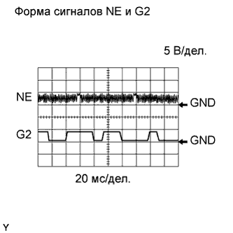
| WAVEFORMS (REFERENCE) |
Camshaft position sensor.
 |
Crankshaft position sensor.
| Item | Content |
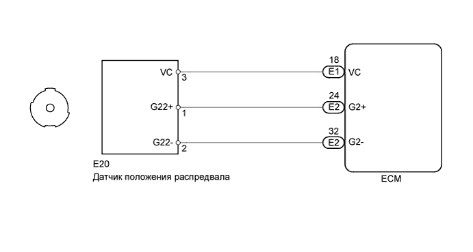
| Tester Connection | (a) E2-24 (G2+) - E2-32 (G2-) (b) E1-27 (NE+) - E1-34 (NE-) |
| Tester Range | 5 V/DIV, 20 msec./DIV |
| Condition | Idle after engine warmed-up |
| 1.CHECK CAMSHAFT POSITION SENSOR (SENSOR POWER SOURCE) |
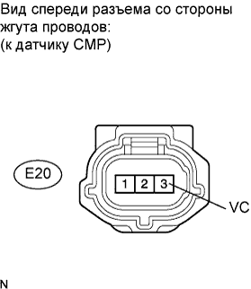 |
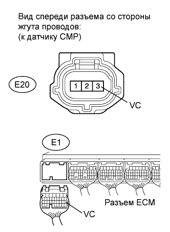
Disconnect the E20 camshaft position sensor connector.
Measure the voltage according to the value(s) in the table below.
| Tester Connection | Switch Condition | Specified Condition |
| E20-3 (VC) - Body ground | Engine switch on (IG) | 4.5 to 5.0 V |
|
| ||||
| OK | |
| 2.CHECK HARNESS AND CONNECTOR (CAMSHAFT POSITION SENSOR - ECM) |
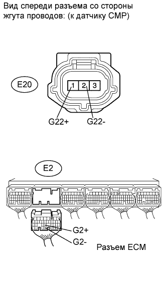 |
Disconnect the E20 camshaft position sensor connector.
Disconnect the E2 ECM connector.
Measure the resistance according to the value(s) in the table below.
| Tester Connection | Condition | Specified Condition |
| E20-1 (G22+) - E2-24 (G2+) | Always | Below 1 Ω |
| E20-2 (G22-) - E2-32 (G2-) | Always | Below 1 Ω |
| Tester Connection | Condition | Specified Condition |
| E20-1 (G22+) or E2-24 (G2+) - Body ground | Always | 10 kΩ or higher |
| E20-2 (G22-) or E2-32 (G2-) - Body ground | Always | 10 kΩ or higher |
|
| ||||
| OK | |
| 3.CHECK SENSOR INSTALLATION (CAMSHAFT POSITION SENSOR) |
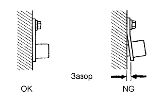 |
Check the sensor installation.
|
| ||||
| OK | |
| 4.INSPECT CAMSHAFT TIMING PLATE |
Check the teeth of the sensor plate.
|
| ||||
| OK | |
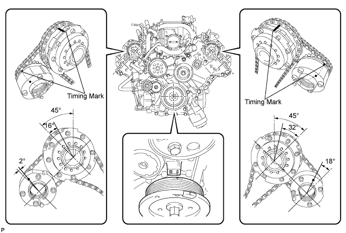
| 5.CHECK VALVE TIMING |
Remove the cylinder head cover bank 1 and bank 2.
Turn the crankshaft pulley, and align its groove with the timing mark "0" of the timing chain cover.
Rotate the crankshaft pulley and align its notch to timing mark 0 of the timing chain cover. Check that the timing marks of the camshaft timing gears and camshaft timing exhaust gears are at the positions shown in the illustration.
Reinstall the cylinder head cover.
|
| ||||
| OK | |
| 6.REPLACE CAMSHAFT POSITION SENSOR |
Replace the camshaft position sensor (see page Нажмите здесь).
| NEXT | |
| 7.CHECK WHETHER DTC OUTPUT RECURS (P1340, P1342 AND/OR P1343) |
Connect the intelligent tester to the DLC3.
Turn the engine switch on (IG).
Turn the tester ON.
Clear DTCs
Start the engine.
Enter the following menus: Powertrain / Engine / DTC / Pending Codes.
Read DTCs.
| Display (DTC Output) | Proceed to |
| No output | A |
| P1340, P1342 and/or P1343 | B |
|
| ||||
| A | ||
| ||
| 8.CHECK HARNESS AND CONNECTOR (CAMSHAFT POSITION SENSOR - ECM) |
 |
Disconnect the E20 camshaft position sensor connector.
Disconnect the E1 ECM connector.
Measure the resistance according to the value(s) in the table below.
| Tester Connection | Condition | Specified Condition |
| E20-3 (VC) - E1-18 (VC) | Always | Below 1 Ω |
| Tester Connection | Condition | Specified Condition |
| E20-3 (VC) or E1-18 (VC) - Body ground | Always | 10 kΩ or higher |
|
| ||||
| OK | ||
| ||
