СИСТЕМА SFI > Цепь контрольной лампы неисправности MIL |
| 1.CHECK THAT MIL IS ILLUMINATED |
Turn the engine switch on (IG).
Check the illumination of the MIL.
| Result | Proceed to |
| MIL remains illuminated (Even after engine switch is turned on (IG) and several seconds have passed, MIL still remains illuminated) | A |
| MIL remains off (Does not illuminate at all) | B |
| MIL illuminates for several seconds, but turns off after engine is started | C |
|
| ||||
|
| ||||
| A | |
| 2.CHECK IF MIL TURNS OFF |
Connect the intelligent tester to the DLC3.
Turn the engine switch on (IG) and turn the tester ON.
Check if DTCs have been stored (see page Нажмите здесь). If DTCs are present, write them down.
Clear the DTCs (see page Нажмите здесь).
Check that the MIL turns off.
|
| ||||
| NG | |
| 3.CHECK HARNESS AND CONNECTOR (FOR SHORT) |
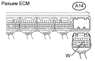 |
Disconnect the A14 ECM connector.
Turn the engine switch on (IG).
Check that the MIL is not illuminated.
|
| ||||
| NG | |
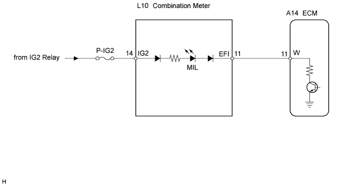
| 4.CHECK HARNESS AND CONNECTOR (COMBINATION METER - ECM) |
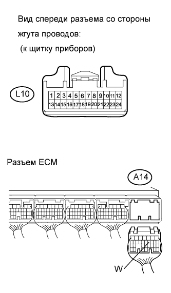 |
Disconnect the L10 combination meter connector.
Disconnect the A14 ECM connector.
Measure the resistance according to the value(s) in the table below.
| Tester Connection | Condition | Specified Condition |
| L10-11 (EFI) - A14-11 (W) | Always | Below 1 Ω |
| L10-11 (EFI) or A14-11 (W) - Body ground | Always | 10 kΩ or higher |
|
| ||||
| OK | ||
| ||
| 5.CHECK THAT ENGINE STARTS |
Start the engine.
| Result | Proceed to |
| Engine starts | A |
| Engine does not start* | B |
|
| ||||
| A | |
| 6.CHECK HARNESS AND CONNECTOR (COMBINATION METER - BODY GROUND) |
|
Disconnect the A14 ECM connector.
Turn the engine switch on (IG).
Measure the voltage according to the value(s) in the table below.
| Tester Connection | Switch Condition | Specified Condition |
| A14-11 (W) - Body ground | Engine switch on (IG) | 11 to 14 V |
|
| ||||
| NG | |
| 7.CHECK HARNESS AND CONNECTOR (COMBINATION METER - ECM) |
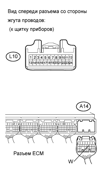 |
Disconnect the L10 combination meter connector.
Disconnect the A14 ECM connector.
Measure the resistance according to the value(s) in the table below.
| Tester Connection | Condition | Specified Condition |
| L10-11 (EFI) - A14-11 (W) | Always | Below 1 Ω |
| L10-11 (EFI) or A14-11 (W) - Body ground | Always | 10 kΩ or higher |
|
| ||||
| OK | ||
| ||
