DTC P0171 System Too Lean (Bank 1) |
DTC P0172 System Too Rich (Bank 1) |
DTC P0174 System Too Lean (Bank 2) |
DTC P0175 System Too Rich (Bank 2) |
| DTC No. | DTC Detection Condition | Trouble Area |
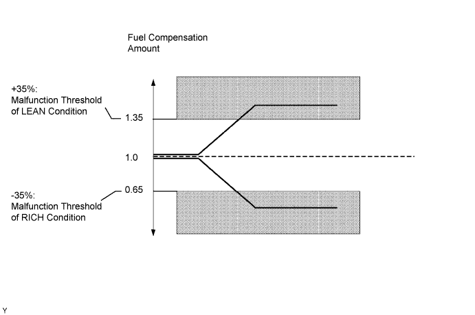
| P0171 P0174 | When air-fuel ratio feedback is stable after warming up engine, fuel trim is considerably in error on LEAN side (2 trip detection logic) |
|
| P0172 P0175 | When air-fuel ratio feedback is stable after warming up engine, fuel trim is considerably in error on RICH side (2 trip detection logic) |
|
| Case | Front HO2 Sensor (Sensor 1) Output Voltage | Rear HO2 Sensor (Sensor 2) Output Voltage | Main Suspected Trouble Area |
| 1 |   |  | - |
| 2 |  | |
|
| 3 | | |
|
| 4 | | |
|
| 1.CHECK ANY OTHER DTCS OUTPUT (IN ADDITION TO DTC P0171, P0172, P0174 OR P0175) |
Connect the intelligent tester to the DLC3.
Turn the engine switch on (IG) and turn the tester ON.
Enter the following menus: Powertrain / Engine / DTC.
Read the DTCs.
| Display (DTC output) | Proceed to |
| P0171, P0172, P0174 or P0175 | A |
| P0171, P0172, P0174 or P0175 and other DTCs | B |
|
| ||||
| A | |
| 2.CHECK CONNECTION OF VENTILATION HOSE |
|
| ||||
| OK | |
| 3.CHECK AIR INDUCTION SYSTEM |
Check the air induction system for vacuum leakage.
|
| ||||
| OK | |
| 4.PERFORM ACTIVE TEST (CONTROL) |
Perform the Active Test Control with the intelligent tester and check the heated oxygen sensor status.
| Related DTCs | Heated Oxygen Sensor Status | Condition and Heated Oxygen Sensor Condition | Misfire | Main Suspected Trouble Area | Go to Step | |||
| B1 S1 | B1 S2 | B2 S1 | B2 S2 | |||||
| N/A | L/R | L/R | L/R | L/R | Normal | None | None | N/A |
| P0171 P0174 | L | L | L | L | Actual is LEAN at all cylinders | May occur | Ventilation hose, air induction system, fuel pressure, MAF or ECT | A |
| P0172 P0175 | R | R | R | R | Actual is RICH at all cylinders | None | Fuel pressure, MAF or ECT | |
| P0171 | L | L | L/R | L/R | Actual is LEAN at bank 1 | May occur | Spark plug, ignition system, injector or exhaust gas leak | B |
| P0174 | L/R | L/R | L | L | Actual is LEAN at bank 2 | |||
| P0172 | R | R | L/R | L/R | Actual is RICH at bank 1 | None | Spark plug, ignition system or injector | C |
| P0175 | L/R | L/R | R | R | Actual is RICH at bank 2 | |||
| P0171 | L | R | L/R | L/R | Heated oxygen sensor (bank 1 sensor 1) malfunction | None | Heated oxygen sensor (bank 1 sensor 1) | D |
| P0174 | L/R | L/R | L | R | Heated oxygen sensor (bank 2 sensor 1) malfunction | None | Heated oxygen sensor (bank 2 sensor 1) | |
| P0172 | R | L | L/R | L/R | Heated oxygen sensor (bank 1 sensor 1) malfunction | None | Heated oxygen sensor (bank 1 sensor 1) | |
| P0175 | L/R | L/R | R | L | Heated oxygen sensor (bank 2 sensor 1) malfunction | None | Heated oxygen sensor (bank 2 sensor 1) | |
|
| ||||
|
| ||||
|
| ||||
|
| ||||
| 5.READ DATA LIST (COOLANT TEMP) |
Connect the intelligent tester to the DLC3.
Enter the following menus: Powertrain / Engine / Data List / Primary / Coolant Temp.
Read the Coolant Temp value when the engine is cold and warmed-up.
|
| ||||
| OK | |
| 6.READ DATA LIST (MAF) |
Enter the following menus: Powertrain / Engine / Data List / Primary / Coolant Temp and MAF.
Allow the engine to idle until the ECT reaches 75°C (167°F).
Read the MAF value at idle rpm and 3000 rpm.
|
| ||||
| OK | |
| 7.CHECK FUEL PRESSURE |
Check the fuel pressure (see page Нажмите здесь).
|
| ||||
| OK | |
| 8.CHECK FOR EXHAUST GAS LEAKAGE |
|
| ||||
| OK | |
| 9.CHECK FOR SPARK AND IGNITION |
|
| ||||
| OK | |
| 10.INSPECT FUEL INJECTOR |
|
| ||||
| OK | |
| 11.INSPECT HEATED OXYGEN SENSOR |
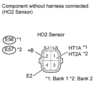 |
Disconnect the E56 and E57 sensor connectors.
Measure the resistance according to the value(s) in the table below.
| Tester Connection | Condition | Specified Condition |
| E56-1 (HT1A) - E56-2 (+B) | Always | 5 to 10 Ω |
| E57-1 (HT2A) - E57-2 (+B) | Always | 5 to 10 Ω |
| E56-1 (HT1A) - E56-4 (E2) | Always | 10 kΩ or higher |
| E57-1 (HT2A) - E57-4 (E2) | Always | 10 kΩ or higher |
|
| ||||
| OK | |
| 12.INSPECT A/F RELAY |
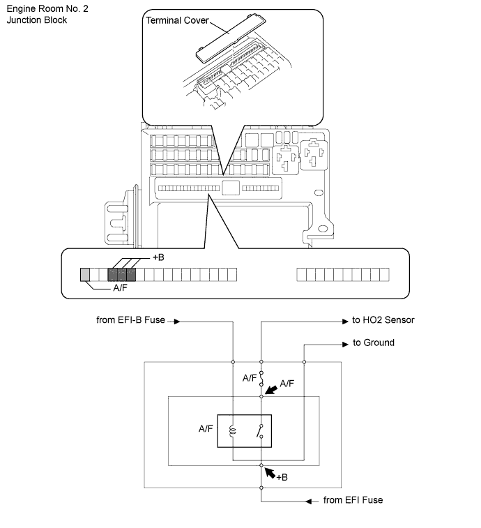
Remove the terminal cover.
Measure the resistance according to the value(s) in the table below.
| Tester Connection | Switch Condition | Specified Condition |
| +B - Body ground | Engine switch on (IG) | 11 - 14 V |
| A/F - Body ground | Engine switch on (IG) | 11 - 14 V |
|
| ||||
| OK | |
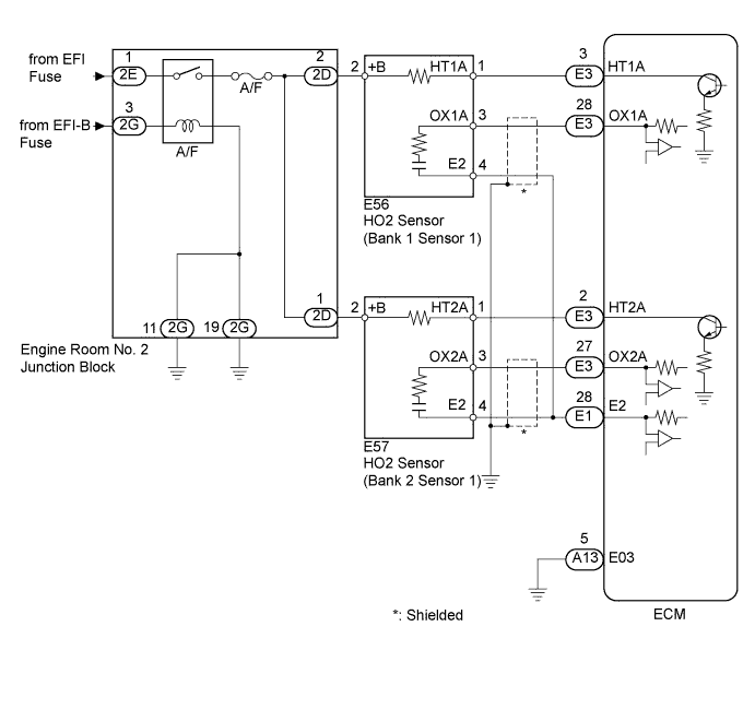
| 13.CHECK HARNESS AND CONNECTOR (HEATED OXYGEN SENSOR (SENSOR 1) - ECM) |
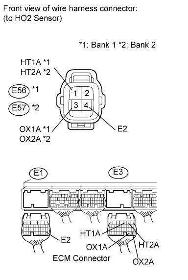 |
Disconnect the E56 and E57 sensor connectors.
Disconnect the E1 and E3 ECM connectors.
Measure the resistance according to the value(s) in the table below.
| Tester Connection | Condition | Specified Condition |
| E56-1 (HT1A) - E3-3 (HT1A) | Always | Below 1 Ω |
| E56-3 (OX1A) - E3-28 (OX1A) | Always | Below 1 Ω |
| E57-1 (HT2A) - E3-2 (HT2A) | Always | Below 1 Ω |
| E57-3 (OX2A) - E3-27 (OX2A) | Always | Below 1 Ω |
| E56-4 (E2) - E1-28 (E2) | Always | Below 1 Ω |
| E57-4 (E2) - E1-28 (E2) | Always | Below 1 Ω |
| E56-1 (HT1A) or E3-3 (HT1A) - Body ground | Always | 10 kΩ or higher |
| E56-3 (OX1A) or E3-28 (OX1A) - Body ground | Always | 10 kΩ or higher |
| E57-1 (HT2A) or E3-2 (HT2A) - Body ground | Always | 10 kΩ or higher |
| E57-3 (OX2A) or E3-27 (OX2A) - Body ground | Always | 10 kΩ or higher |
|
| ||||
| OK | |
| 14.REPLACE HEATED OXYGEN SENSOR |
Replace the heated oxygen sensor (see page Нажмите здесь).
| NEXT | |
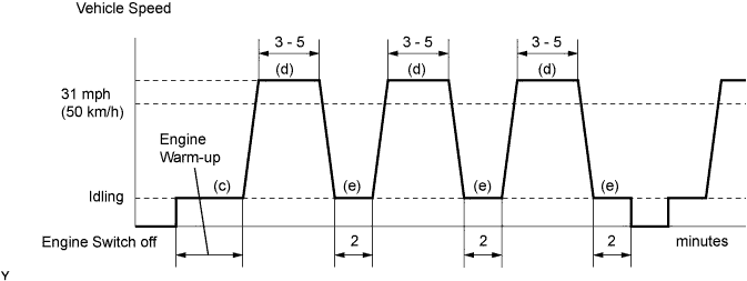
| 15.PERFORM CONFIRMATION DRIVING PATTERN |
| NEXT | ||
| ||
