DTC P0705 Transmission Range Sensor Circuit Malfunction (PRNDL Input) |
| DTC No. | DTC Detection Condition | Trouble Area |
| P0705 |
|
|
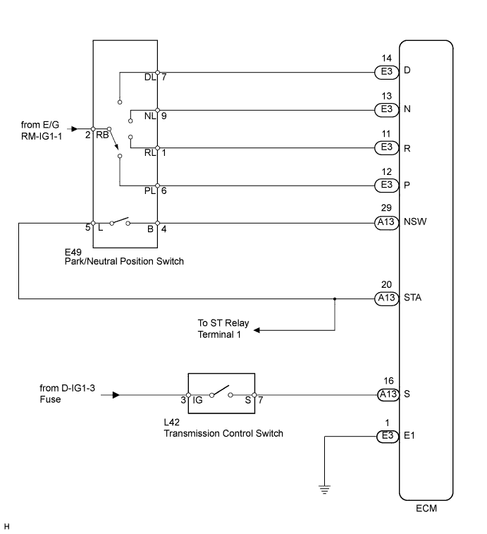
| Park/neutral position switch | The park/neutral position switch sends only one signal to the ECM. |
| DATA LIST |
Warm up the engine.
Turn the engine switch off.
Connect the intelligent tester to the DLC3.
Turn the engine switch on (IG).
Turn the tester ON.
Enter the following menus: Powertrain / ECT / Data List.
According to the display on the tester, read the "Data List".
| Tester Display | Measurement Item/Range | Normal Condition | Diagnostic Note |
| Sift SW Status (R Range) | PNP switch status/ ON or OFF | Shift lever is:
| When shift lever position displayed on intelligent tester differs from actual position, adjustment of PNP switch or shift cable may be incorrect |
| Sift SW Status (P Range) | PNP switch status/ ON or OFF | Shift lever is:
| When shift lever position displayed on intelligent tester differs from actual position, adjustment of PNP switch or shift cable may be incorrect |
| Sift SW Status (N Range) | PNP switch status/ ON or OFF | Shift lever is:
| When shift lever position displayed on intelligent tester differs from actual position, adjustment of PNP switch or shift cable may be incorrect |
| Sift SW Status (D Range) | PNP switch status/ ON or OFF | Shift lever is:
| When shift lever position displayed on intelligent tester differs from actual position, adjustment of PNP switch or shift cable may be incorrect |
| Neutral Position SW Signal | PNP switch status/ ON or OFF | Shift lever is:
| When shift lever position displayed on intelligent tester differs from actual position, adjustment of PNP switch or shift cable may be incorrect |
| Sports Mode Selection SW | Sport Mode Select Switch Status/ ON or OFF | Shift lever position is: S, "+" and "-": ON Except S, "+" and "-": OFF | - |
| 1.READ VALUE OF INTELLIGENT TESTER |
Connect the intelligent tester to the DLC3.
Turn the engine switch on (IG).
Turn the tester ON.
Enter the following menus: Powertrain / ECT / Data List.
According to the display on the tester, read the "Data List".
| Tester Display | Shift Lever Position | Specified Condition |
| Neutral Position SW Signal | N → R → P | ON → OFF → ON |
| Sift SW Status (R Range) | N → R | OFF → ON |
| Sift SW Status (P Range) | P | ON |
| Sift SW Status (N Range) | N | ON |
| Sift SW Status (D Range) | N → D | OFF → ON |
|
| ||||
| NG | |
| 2.CHECK HARNESS AND CONNECTOR (BATTERY - PARK/NEUTRAL POSITION SWITCH) |
 |
Disconnect the E49 park/neutral position switch.
Turn the engine switch on (IG).
Measure the voltage according to the value(s) in the table below.
| Tester Connection | Switch Condition | Specified Condition |
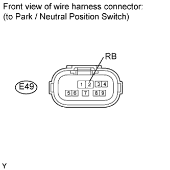
| E49-2 (RB) - Body ground | Engine switch on (IG) | 11 to 14 V |
|
| ||||
| OK | |
| 3.INSPECT PARK/NEUTRAL POSITION SWITCH ASSEMBLY |
 |
Disconnect the E49 park/neutral position switch connector.
Measure the resistance according to the value(s) in the table below when the shift lever is moved to each position.
| Tester Connection | Shift Lever Position | Specified Condition |
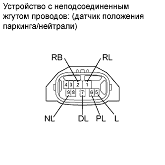
| 2 (RB) - 6 (PL) 4 (B) - 5 (L) | P | Below 1 Ω |
| Except P | 10 kΩ or higher | |
| 1 (RL) - 2 (RB) | R | Below 1 Ω |
| Except R | 10 kΩ or higher | |
| 2 (RB) - 9 (NL) 4 (B) - 5 (L) | N | Below 1 Ω |
| Except N | 10 kΩ or higher | |
| 2 (RB) - 7 (DL) | D, S, "+" and "-" | Below 1 Ω |
| Except D, S, "+" and "-" | 10 kΩ or higher |
Reconnect the E49 park/neutral position switch.
|
| ||||
| OK | |
| 4.CHECK HARNESS AND CONNECTOR (ECM - PARK/NEUTRAL POSITION SWITCH) |
 |
Turn the engine switch on (IG).
 |
Measure the voltage according to the value(s) in the table below.
| Tester Connection | Shift Lever Position | Switch Condition | Specified Condition |
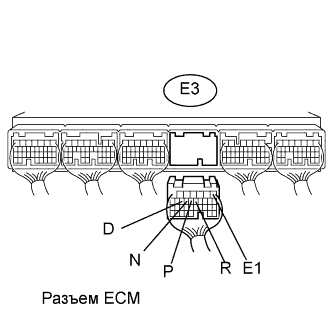
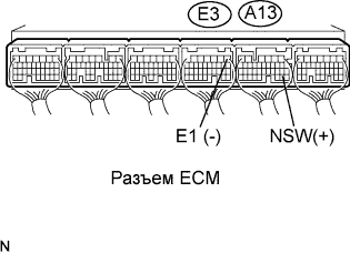
| A13-29 (NSW) - E3-1 (E1) | P or N | Engine switch on (IG) | 0 to 1.5 V |
| Except P or N | Engine switch on (IG) | 11 to 14 V |
Turn the engine switch off.
Disconnect the E3 ECM connector.
Turn the engine switch on (IG).
Measure the voltage according to the value(s) in the table below.
| Tester Connection | Shift Lever Position | Switch Condition | Specified Condition |
| E3-12 (P) - E3-1 (E1) | P | Engine switch on (IG) | 11 to 14 V |
| Except P | Engine switch on (IG) | 0 to 1.5 V | |
| E3-11 (R) - E3-1 (E1) | R | Engine switch on (IG) | 11 to 14 V |
| Except R | Engine switch on (IG) | 0 to 1.5 V | |
| E3-13 (N) - E3-1 (E1) | N | Engine switch on (IG) | 11 to 14 V |
| Except N | Engine switch on (IG) | 0 to 1.5 V | |
| E3-14 (D) - E3-1 (E1) | D | Engine switch on (IG) | 11 to 14 V |
| Except D | Engine switch on (IG) | 0 to 1.5 V |
|
| ||||
| OK | ||
| ||
| 5.READ VALUE OF INTELLIGENT TESTER |
Connect the intelligent tester to the DLC3.
Turn the engine switch on (IG).
Turn the tester ON.
Enter the following menus: Powertrain / ECT / Data List.
According to the display on the tester, read the "Data List".
| Tester Display | Shift Lever Position | Specified Condition |
| Sports Mode Selection SW | D → S | OFF → ON |
|
| ||||
| NG | |
| 6.INSPECT TRANSMISSION CONTROL SWITCH |
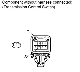 |
Disconnect the L42 transmission control switch connector of the shift lock control unit assembly.
Measure the resistance according to the value(s) in the table below when the shift lever is moved to each position.
| Tester Connection | Shift Lever Position | Condition | Specified Condition |
| 3 (IG) - 7 (S) | S, "+" and "-" | Always | Below 1 Ω |
| Except S, "+" and "-" | Always | 10 kΩ or higher |
|
| ||||
| OK | |
| 7.CHECK HARNESS AND CONNECTOR (TRANSMISSION CONTROL SWITCH - ECM) |
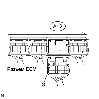 |
Disconnect the A13 ECM connector.
Turn the engine switch on (IG).
Measure the voltage according to the value(s) in the table below.
| Tester Connection | Shift Lever Position | Switch Condition | Specified Condition |
| A13-16 (S) - Body ground | S, "+" and "-" | Engine switch on (IG) | 11 to 14 V* |
| Except S, "+" and "-" | Engine switch on (IG) | 0 to 1.5 V* |
|
| ||||
| OK | ||
| ||
