СИСТЕМА SFI > Цепь управления топливным насосом |
| 1.CHECK FUEL PUMP OPERATION |
Check if there is pressure in the fuel inlet hose (see page Нажмите здесь).
|
| ||||
| NG | |
| 2.PERFORM ACTIVE TEST USING INTELLIGENT TESTER (OPERATE C/OPN RELAY) |
Connect an intelligent tester to the DLC3.
Turn the engine switch on (IG) and turn the tester ON.
Enter the following menus: Powertrain / Engine / Active Test / Control the Fuel Pump / Speed.
Check whether operating sounds can be heard while operating the relay using the tester.
|
| ||||
| NG | |
| 3.INSPECT C/OPN RELAY |
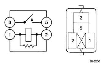 |
Remove the C/OPN relay from the engine room No. 2 relay block.
Measure the resistance according to the value(s) in the table below.
| Tester Connection | Condition | Specified Condition |
| 3 - 5 | When no battery voltage applied to terminals 1 and 2 | 10 kΩ or higher |
| 3 - 5 | When battery voltage applied to terminals 1 and 2 | Below 1 Ω |
|
| ||||
| OK | |
| 4.INSPECT ECM (FC VOLTAGE) |
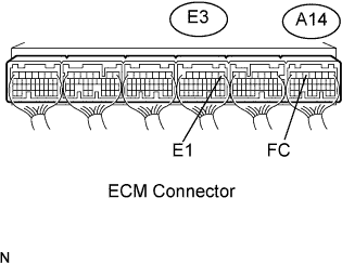 |
Turn the engine switch on (IG).
Measure the voltage according to the value(s) in the table below.
| Tester Connection | Switch Condition | Specified Condition |
| A14-5 (FC) - E3-1 (E1) | Engine switch on (IG) | 11 to 14 V |
|
| ||||
| NG | ||
| ||
| 5.INSPECT ECM POWER SOURCE CIRCUIT |
Inspect the ECM power source circuit (see page Нажмите здесь).
|
| ||||
| OK | |
| 6.INSPECT F/PMP RELAY |
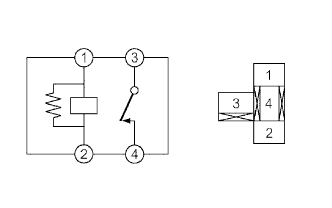 |
Remove the F/PMP relay from the engine room No. 2 relay block.
Measure the resistance according to the value(s) in the table below.
| Tester Connection | Condition | Specified Condition |
| 3 - 4 | When no battery voltage is applied to terminals 1 and 2 | Below 1 Ω |
| 3 - 4 | When battery voltage is applied to terminals 1 and 2 | 10 kΩ or more |
|
| ||||
| OK | |
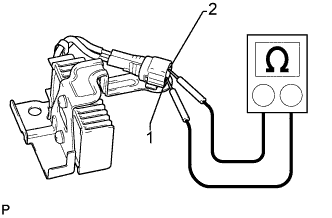
| 7.INSPECT FUEL PUMP ASSEMBLY |
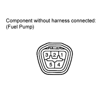 |
Inspect the fuel pump resistance.
Measure the resistance according to the value(s) in the table below.
| Tester Connection | Condition | Specified Condition |
| 4 - 5 | 20°C (68°F) | 0.2 to 3.0 Ω |
Inspect the fuel pump operation.
Apply battery voltage to both terminals. Check that the pump operates.
|
| ||||
| OK | |
| 8.CHECK HARNESS AND CONNECTOR (FUEL PUMP - F/PMP RELAY, FUEL PUMP - BODY GROUND) |
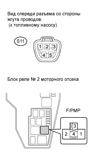 |
Check the harness and connector between the fuel pump and F/PMP relay.
Disconnect the S11 fuel pump connector.
Remove the F/PMP relay from the engine room No. 2 relay block.
Measure the resistance according to the value(s) in the table below.
| Tester Connection | Condition | Specified Condition |
| S11-4 - F/PMP relay (3) | Always | Below 1 Ω |
| Tester Connection | Condition | Specified Condition |
| S11-4 or F/PMP relay (3) - Body ground | Always | 10 kΩ or higher |
Check the harness and connector between the fuel pump and body ground.
Disconnect the S11 fuel pump connector.
Measure the resistance according to the value(s) in the table below.
| Tester Connection | Condition | Specified Condition |
| S11-5 - Body ground | Always | Below 1 Ω |
|
| ||||
| OK | |
| 9.CHECK HARNESS AND CONNECTOR (C/OPN RELAY - F/PMP RELAY) |
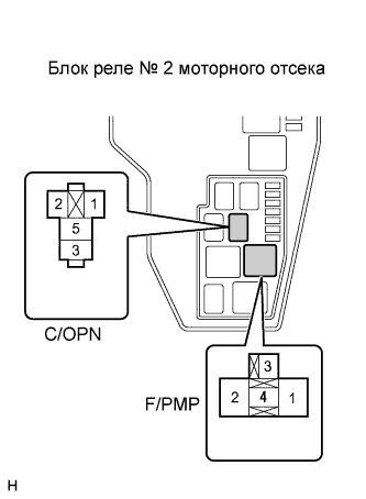 |
Remove the C/OPN relay and F/PMP relay from the engine room No. 2 relay block.
Measure the resistance according to the value(s) in the table below.
| Tester Connection | Condition | Specified Condition |
| C/OPN relay (3) - F/PMP relay (4) | Always | Below 1 Ω |
| Tester Connection | Condition | Specified Condition |
| C/OPN relay (3) or F/PMP relay (4) - Body ground | Always | 10 kΩ or higher |
|
| ||||
| OK | ||
| ||
| 10.INSPECT F/PMP RELAY |
|
Remove the F/PMP relay from the engine room No. 2 relay block.
Measure the resistance according to the value(s) in the table below.
| Tester Connection | Condition | Specified Condition |
| 3 - 4 | When no battery voltage is applied to terminals 1 and 2 | Below 1 Ω |
| 3 - 4 | When battery voltage is applied to terminals 1 and 2 | 10 kΩ or more |
|
| ||||
| OK | |
| 11.INSPECT FUEL PUMP RESISTOR (RESISTANCE) |
 |
Inspect the fuel pump resistor resistance.
Measure the resistance according to the value(s) in the table below.
| Tester Connection | Condition | Specified Condition |
| 1 - 2 | 20°C (68°F) | 0.941 to 0.999 Ω |
|
| ||||
| OK | |
| 12.CHECK HARNESS AND CONNECTOR (F/PMP RELAY - FUEL PUMP RESISTOR - FUEL PUMP) |
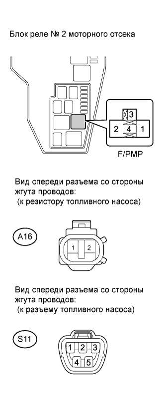 |
Check the harness and connector between the fuel pump relay and fuel pump resistor.
Remove the F/PMP relay from the engine room No. 2 relay block.
Disconnect the A16 fuel pump resistor connector.
Check the resistance.
| Tester Connection | Condition | Specified Condition |
| F/PMP relay (4) - A16-1 | Always | Below 1 Ω |
| Tester Connection | Condition | Specified Condition |
| F/PMP relay (4) or A16-1 - Body ground | Always | 10 kΩ or higher |
Check the harness and connector between the fuel pump resistor and fuel pump.
Disconnect the A16 fuel pump resistor connector.
Disconnect the S11 fuel pump connector.
Check the resistance.
| Tester Connection | Condition | Specified Condition |
| A16-2 - S11-4 | Always | Below 1 Ω |
| Tester Connection | Condition | Specified Condition |
| A16-2 or S11-4 - Body ground | Always | 10 kΩ or higher |
|
| ||||
| NG | ||
| ||
