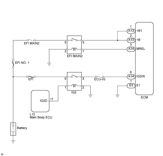
СИСТЕМА SFI > Цепь питания ECM |
| 1.INSPECT ECM (+B, +B2 VOLTAGE) |
 |
Turn the engine switch on (IG).
Measure the voltage according to the value(s) in the table below.
| Tester Connection | Switch Condition | Specified Condition |
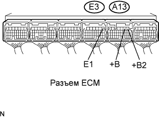
| A13-2 (+B) - E3-1 (E1) | Engine switch on (IG) | 11 to 14 V |
| A13-1 (+B1) - E3-1 (E1) | Engine switch on (IG) | 11 to 14 V |
|
| ||||
| NG | |
| 2.CHECK HARNESS AND CONNECTOR (ECM - BODY GROUND) |
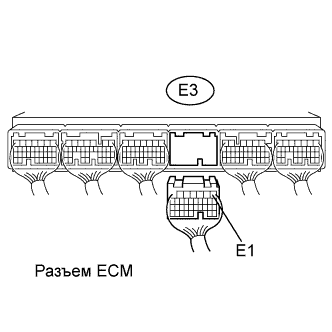 |
Disconnect the E3 ECM connector.
Measure the resistance according to the value(s) in the table below.
| Tester Connection | Condition | Specified Condition |
| E3-1 (E1) - Body ground | Always | Below 1 Ω |
|
| ||||
| OK | |
| 3.INSPECT ECM (IGSW VOLTAGE) |
 |
Turn the engine switch on (IG).
Measure the voltage according to the value(s) in the table below.
| Tester Connection | Switch Condition | Specified Condition |
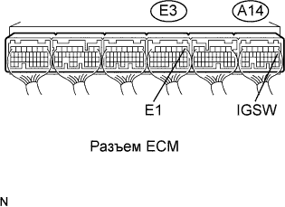
| A14-8 (IGSW) - E3-1 (E1) | Engine switch on (IG) | 11 to 14 V |
|
| ||||
| NG | |
| 4.CHECK FUSE (ECU-IG) |
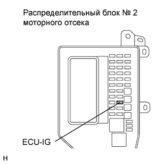 |
Remove the ECU-IG fuse from the engine room No. 2 junction block.
Measure the resistance of the fuse.
| Tester Connection | Condition | Specified Condition |
| ECU-IG fuse | Always | Below 1 Ω |
|
| ||||
| OK | |
| 5.INSPECT IGNITION RELAY NO. 2 |
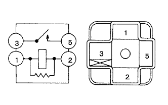 |
Remove the IG2 relay from the engine room No. 2 junction block.
Measure the resistance according to the value(s) in the table below.
| Tester Connection | Condition | Specified Condition |
| 3 - 5 | When no battery voltage applied to terminals 1 and 2 | 10 kΩ or higher |
| 3 - 5 | When battery voltage applied to terminals 1 and 2 | Below 1 Ω |
|
| ||||
| OK | ||
| ||
| 6.INSPECT ECM (MREL VOLTAGE) |
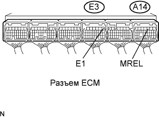 |
Turn the engine switch on (IG).
Measure the voltage according to the value(s) in the table below.
| Tester Connection | Switch Condition | Specified Condition |
| A14-3 (MREL) - E3-1 (E1) | Engine switch on (IG) | 11 to 14 V |
|
| ||||
| OK | |
| 7.CHECK FUSE (EFI MAIN NO. 2) |
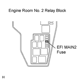 |
Remove the EFI MAIN2 fuse from the engine room No. 2 relay block.
Measure the resistance of the fuse.
| Tester Connection | Condition | Specified Condition |
| EFI MAIN2 fuse | Always | Below 1 Ω |
|
| ||||
| OK | |
| 8.INSPECT EFI MAIN2 RELAY |
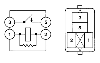 |
Remove the integration relay from the engine room No. 2 relay block.
Measure the resistance according to the value(s) in the table below.
| Tester Connection | Condition | Specified Condition |
| 3 - 5 | When no battery voltage applied to terminals 1 and 2 | 10 kΩ or higher |
| When battery voltage applied to terminals 1 and 2 | Below 1 Ω |
|
| ||||
| OK | |
| 9.CHECK HARNESS AND CONNECTOR (EFI MAIN2 RELAY- ECM, EFI MAIN2 RELAY - BODY GROUND) |
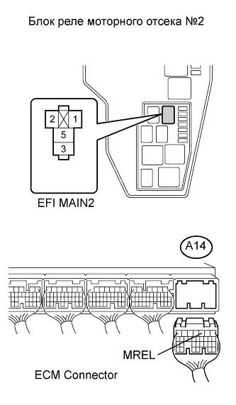 |
Check the harness and the connectors between the integration relay and the ECM.
Remove the EFI MAIN2 relay from the engine room No. 2 relay block.
Disconnect the A14 ECM connector.
Measure the resistance according to the value(s) in the table below.
| Tester Connection | Condition | Specified Condition |
| EFI MAIN2 (1) - A14-3 (MREL) | Always | Below 1 Ω |
| Tester Connection | Condition | Specified Condition |
| EFI MAIN2 (1) or A14-3 (MREL) - Body ground | Always | 10 kΩ or higher |
Check the harness and the connectors between the EFI MAIN2 relay and body ground.
Remove the EFI MAIN2 relay from the engine room No. 2 relay block.
Measure the resistance according to the value(s) in the table below.
| Tester Connection | Condition | Specified condition |
| EFI MAIN2 (2) - Body ground | Always | Below 1 Ω |
|
| ||||
| OK | ||
| ||
