СИСТЕМА SFI > Цепь функции полуавтоматического запуска двигателя |
| 1.CHECK OPERATION OF CRANKING |
When starting the engine, check whether the starter motor starts.
| Starter Condition | Proceed to |
| Not operating | A |
| Operating | B |
|
| ||||
| A | |
| 2.CHECK SMART ACCESS SYSTEM WITH PUSH-BUTTON START (ENGINE DOES NOT START) |
Refer to Smart Access System With Push-button Start [Engine does not start] (see page Нажмите здесь).
|
| ||||
| OK | |
| 3.READ VALUE OF INTELLIGENT TESTER (STARTER SIGNAL) |
Connect the intelligent tester to the DLC3.
Turn the engine switch on (IG) and turn the tester ON.
Enter the following menus: Powertrain / Engine / Data List / Starter Signal.
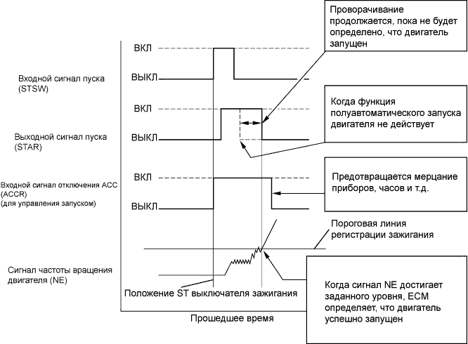
Check the result when the engine switch is turned on (IG) and the engine is started.
| Starter Signal | Engine Switch Position |
| OFF | on (IG) |
| ON | ENGINE START |
|
| ||||
| NG | |
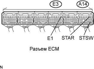
| 4.INSPECT ECM (STAR AND STSW VOLTAGE) |
 |
Measure the voltage according to the value(s) in the table below while cranking the engine.
| Tester Connection | Switch Condition | Specified Condition |
| A14-2 (STAR) - E3-1 (E1) | Engine cranking | 11 to 14 V |
| A14-27 (STSW) - E3-1 (E1) | Engine cranking | 11 to 14 V |
| Terminal STAR | Terminal STSW | Proceed to |
| 11 to 14 V | 11 to 14 V | A |
| 0 V | 11 to 14 V | B |
| 0 V | 0 V | C |
|
| ||||
|
| ||||
| A | |
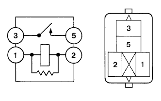
| 5.INSPECT ST CUT RELAY |
 |
Remove the ST CUT relay from the engine room No. 2 relay block.
Measure the resistance according to the value(s) in the table below.
| Tester Connection | Condition | Specified Condition |
| 3 - 5 | When no battery voltage applied to terminals 1 and 2 | 10 kΩ or higher |
| 3 - 5 | When battery voltage applied to terminals 1 and 2 | Below 1 Ω |
|
| ||||
| OK | |
| 6.INSPECT PARK/NEUTRAL POSITION SWITCH ASSEMBLY |
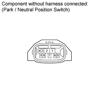 |
Disconnect the park/neutral position (PNP) switch connector.
Measure the resistance according to the value(s) in the table below.
| Tester Connection | Condition | Specified Condition |
| 4 - 5 | Shift position P | Below 1 Ω |
| 4 - 5 | Shift position N | Below 1 Ω |
|
| ||||
| OK | |
| 7.CHECK HARNESS AND CONNECTOR (ST CUT RELAY - PARK/NEUTRAL POSITION SWITCH, ECM) |
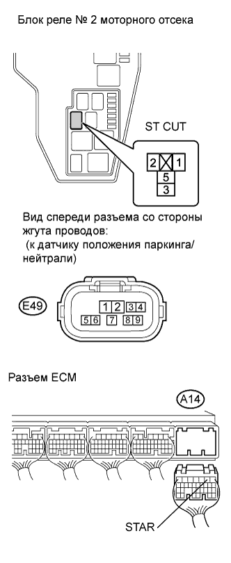 |
Remove the ST CUT relay from the engine room No. 2 relay block.
Disconnect the E45 switch connector.
Disconnect the A14 ECM connector.
Measure the resistance according to the value(s) in the table below.
| Tester Connection | Condition | Specified condition |
| ST CUT (3) - Park / neutral position switch (4) | Always | Below 1 Ω |
| ST CUT (5) - A14-2 (STAR) | Always | Below 1 Ω |
| Tester Connection | Condition | Specified condition |
| ST CUT (3) or Park / neutral position switch (4) - Body ground | Always | 10 kΩ or higher |
| ST CUT (5) or A14-2 (STAR) - Body ground | Always | 10 kΩ or higher |
|
| ||||
| OK | |
| 8.CHECK ENGINE ROOM NO. 2 RELAY BLOCK (ST CUT RELAY - IG2 RELAY, BODY GROUND) |
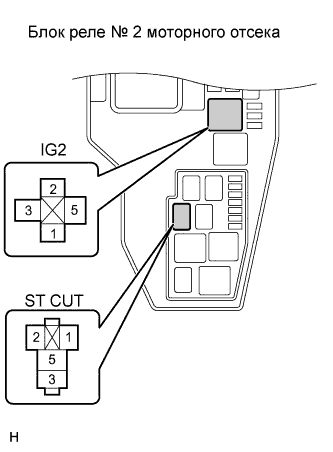 |
Remove the IG2 relay from the engine room No. 2 relay block.
Remove the ST CUT relay from the engine room No. 2 relay block.
Measure the resistance according to the value(s) in the table below.
| Tester Connection | Condition | Specified condition |
| ST CUT (2) - IG2 (3) | Always | Below 1 Ω |
| ST CUT (1) - Body ground | Always | Below 1 Ω |
| Tester Connection | Condition | Specified condition |
| ST CUT (2) or IG2 (3) - Body ground | Always | 10 kΩ or higher |
|
| ||||
| OK | ||
| ||
| 9.INSPECT STARTER RELAY |
|
Remove the starter relay from the engine room No. 2 relay block.
Measure the resistance according to the value(s) in the table below.
| Tester Connection | Condition | Specified Condition |
| 3 - 5 | When no battery voltage applied to terminals 1 and 2 | 10 kΩ or higher |
| 3 - 5 | When battery voltage applied to terminals 1 and 2 | Below 1 Ω |
|
| ||||
| OK | |
| 10.CHECK HARNESS AND CONNECTOR (ST RELAY - PARK/NEUTRAL POSITION SWITCH, BODY GROUND) |
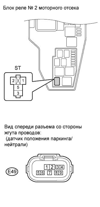 |
Remove the ST relay from the engine room No. 2 relay block.
Disconnect the E49 switch connector.
Measure the resistance according to the value(s) in the table below.
| Tester Connection | Condition | Specified Condition |
| ST relay (1) - Park / neutral position switch (5) | Always | Below 1 Ω |
| ST relay (2) - Body ground | Always | Below 1 Ω |
| Tester Connection | Condition | Specified Condition |
| ST relay (1) or Park / neutral position switch (5) - Body ground | Always | 10 kΩ or higher |
|
| ||||
| OK | |
| 11.INSPECT STARTER ASSEMBLY |
Inspect the starter assembly for 1.6 kW type (see page Нажмите здесь) or starter assembly for 2.0 kW type (see page Нажмите здесь).
|
| ||||
|
| ||||
| OK | |
| 12.CHECK HARNESS AND CONNECTOR (STARTER ASSEMBLY - ST RELAY, BATTERY) |
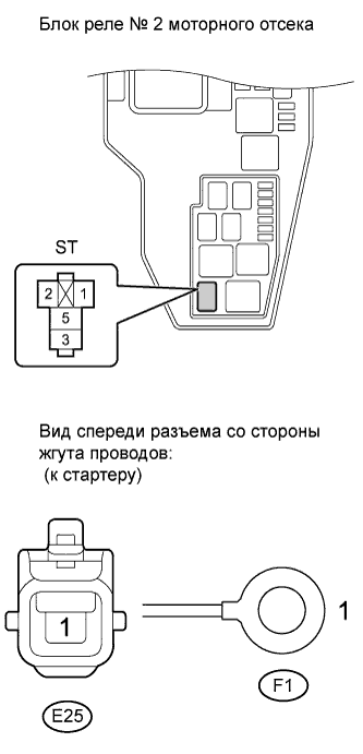 |
Remove the ST relay from the engine room No. 2 relay block.
Disconnect the E25 and F1 starter connectors.
Disconnect the cable from the positive battery terminal.
Measure the resistance according to the value(s) in the table below.
| Tester Connection | Condition | Specified Condition |
| ST relay (3) - E25-1 | Always | Below 1 Ω |
| F1-1 - Battery cable (+) | Always | Below 1 Ω |
| Tester Connection | Condition | Specified Condition |
| ST relay (3) or E25-1 - Body ground | Always | 10 kΩ or higher |
| F1-1 or Battery cable (+) - Body ground | Always | 10 kΩ or higher |
|
| ||||
| OK | ||
| ||
