DTC P0504 Brake Switch "A" / "B" Correlation |
| Signals | Brake Pedal Released | In Transition | Brake Pedal Depressed |
| STP | OFF | ON | ON |
| ST1- | ON | ON | OFF |
| DTC No. | DTC Detection Condition | Trouble Area |
| P0504 | Conditions (a), (b) and (c) continue for 0.5 seconds or more (1 trip detection logic)
|
|
| 1.CHECK OPERATION OF STOP LIGHT |
Check whether the stop lights turn on and off normally when the brake pedal is depressed and released.
|
| ||||
| OK | |
| 2.INSPECT STOP LIGHT SWITCH ASSEMBLY |
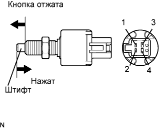 |
Remove the stop light switch assembly.
Measure the resistance according to the value(s) in the table below.
| Tester Connection | Switch Condition | Specified Condition |
| 1 - 2 | Switch pin free | Below 1 Ω |
| 3 - 4 | 10 kΩ or higher | |
| 1 - 2 | Switch pin pushed in | 10 kΩ or higher |
| 3 - 4 | Below 1 Ω |
|
| ||||
| OK | |
| 3.READ VALUE USING INTELLIGENT TESTER (STP SIGNAL AND ST1- VOLTAGE) |
 |
Connect the intelligent tester to the DLC3.
Turn the engine switch on (IG) and turn the tester ON.
Enter the following menus: Powertrain / Engine / Data List / Stop Light Switch.
Check the STP signal when the brake pedal is depressed and released.
| Brake Pedal Operation | Specified Condition |
| Depressed | STP signal ON |
| Released | STP signal OFF |
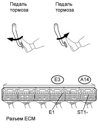
Measure the voltage according to the value(s) in the table below.
| Tester Connection | Condition | Specified Condition |
| A14-12 (ST1-) - E3-1 (E1) | Brake pedal depressed | Below 1.5 V |
| Brake pedal released | 7.5 to 14 V |
|
| ||||
| NG | |
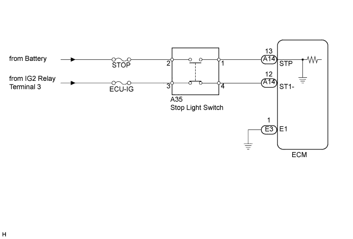
| 4.CHECK HARNESS AND CONNECTOR (STOP LIGHT SWITCH - ECM) |
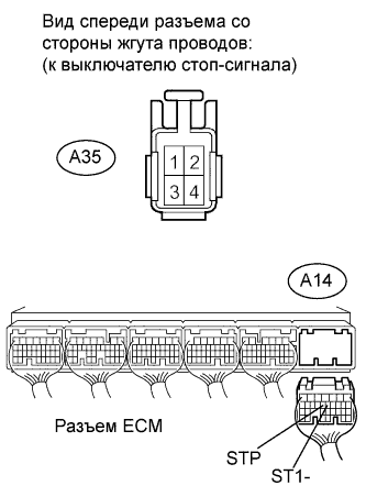 |
Disconnect the A35 stop light switch connector.
Disconnect the A14 ECM connector.
Measure the resistance according to the value(s) in the table below.
| Tester Connection | Condition | Specified Condition |
| A35-1 (Stop light switch) - A14-13 (STP) | Always | Below 1 Ω |
| A35-4 (Stop light switch) - A14-12 (ST1-) | Always |
| Tester Connection | Condition | Specified Condition |
| A35-1 (Stop light switch) or A14-13 (STP) - Body ground | Always | 10 kΩ or higher |
| A35-4 (Stop light switch) or A14-12 (ST1-) - Body ground | Always |
|
| ||||
| OK | ||
| ||
