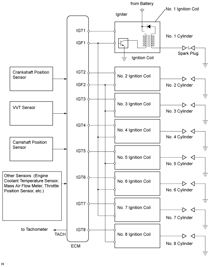
DTC P0351 Ignition Coil "A" Primary / Secondary Circuit |
DTC P0352 Ignition Coil "B" Primary / Secondary Circuit |
DTC P0353 Ignition Coil "C" Primary / Secondary Circuit |
DTC P0354 Ignition Coil "D" Primary / Secondary Circuit |
DTC P0355 Ignition Coil "E" Primary / Secondary Circuit |
DTC P0356 Ignition Coil "F" Primary / Secondary Circuit |
DTC P0357 Ignition Coil "G" Primary / Secondary Circuit |
DTC P0358 Ignition Coil "H" Primary / Secondary Circuit |
| DTC No. | DTC Detection Condition | Trouble Area |
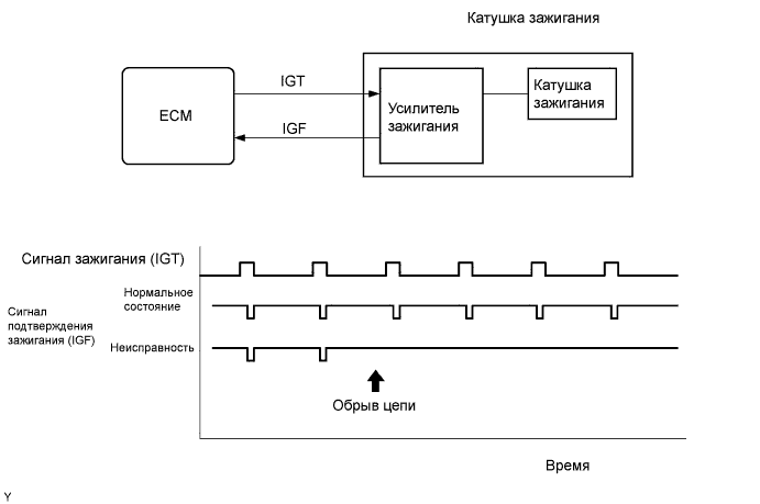
| P0351 P0352 P0353 P0354 P0355 P0356 P0357 P0358 | No IGF signal to ECM while engine running (1 trip detection logic) |
|
 |
| Item | Content |
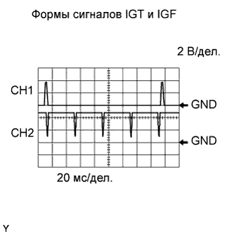
| Terminal | CH1: IGT1, IGT2, IGT3, IGT4, IGT5, IGT6, IGT7, IGT8 - E1 CH2: IGF1, IGF2 - E1 |
| Equipment Setting | 2 V/DIV. 20 msec./DIV. |
| Condition | Cranking or idling |
| 1.PERFORM SIMULATION TEST |
Clear the DTC(s) (see page Нажмите здесь).
Change the arrangement of the ignition coils (with igniters).
Perform a simulation test.
| Display (DTC Output) | Proceed to |
| Same DTCs (that have been erased) | A |
| Other DTCs | B |
|
| ||||
| A | |
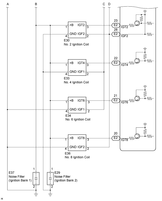
| 2.INSPECT IGNITION COIL ASSEMBLY (POWER SOURCE) |
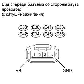 |
Disconnect the E38, E30, E41, E33, E42, E34, E45 or E36 ignition coil connector.
Turn the engine switch on (IG).
Measure the voltage according to the value(s) in the table below.
| Tester Connection | Switch Condition | Specified Condition |
| E38-1 (+B) - Body ground | Engine switch on (IG) | 11 to 14 V |
| E30-1 (+B) - Body ground | Engine switch on (IG) | 11 to 14 V |
| E41-1 (+B) - Body ground | Engine switch on (IG) | 11 to 14 V |
| E33-1 (+B) - Body ground | Engine switch on (IG) | 11 to 14 V |
| E42-1 (+B) - Body ground | Engine switch on (IG) | 11 to 14 V |
| E34-1 (+B) - Body ground | Engine switch on (IG) | 11 to 14 V |
| E45-1 (+B) - Body ground | Engine switch on (IG) | 11 to 14 V |
| E36-1 (+B) - Body ground | Engine switch on (IG) | 11 to 14 V |
Measure the resistance according to the value(s) in the table below.
| Tester Connection | Condition | Specified Condition |
| E38-4 (GND) - Body ground | Always | Below 1 Ω |
| E30-4 (GND) - Body ground | Always | Below 1 Ω |
| E41-4 (GND) - Body ground | Always | Below 1 Ω |
| E33-4 (GND) - Body ground | Always | Below 1 Ω |
| E42-4 (GND) - Body ground | Always | Below 1 Ω |
| E34-4 (GND) - Body ground | Always | Below 1 Ω |
| E45-4 (GND) - Body ground | Always | Below 1 Ω |
| E36-4 (GND) - Body ground | Always | Below 1 Ω |
|
| ||||
| OK | |
| 3.CHECK HARNESS AND CONNECTOR (IGNITION COIL ASSEMBLY - ECM) |
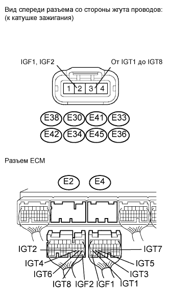 |
Disconnect the E38, E30, E41, E33, E42, E34, E45 or E36 ignition coil connector.
Disconnect the E2 and E4 ECM connectors.
Measure the resistance according to the value(s) in the table below.
| Tester Connection | Condition | Specified Condition |
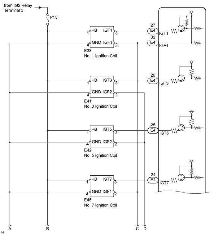
| E38-3 (IGT1) - E4-27 (IGT1) | Always | Below 1 Ω |
| E30-3 (IGT2) - E2-23 (IGT2) | Always | Below 1 Ω |
| E41-3 (IGT3) - E4-26 (IGT3) | Always | Below 1 Ω |
| E33-3 (IGT4) - E2-22 (IGT4) | Always | Below 1 Ω |
| E42-3 (IGT5) - E4-25 (IGT5) | Always | Below 1 Ω |
| E34-3 (IGT6) - E2-21 (IGT6) | Always | Below 1 Ω |
| E45-3 (IGT7) - E4-24 (IGT7) | Always | Below 1 Ω |
| E36-3 (IGT8) - E2-20 (IGT8) | Always | Below 1 Ω |
| Tester Connection | Condition | Specified Condition |
| E38-3 (IGT1) or E4-27 (IGT1) - Body ground | Always | 10 kΩ or higher |
| E30-3 (IGT2) or E2-23 (IGT2) - Body ground | Always | 10 kΩ or higher |
| E41-3 (IGT3) or E4-26 (IGT3) - Body ground | Always | 10 kΩ or higher |
| E33-3 (IGT4) or E2-22 (IGT4) - Body ground | Always | 10 kΩ or higher |
| E42-3 (IGT5) or E4-25 (IGT5) - Body ground | Always | 10 kΩ or higher |
| E34-3 (IGT6) or E2-21 (IGT6) - Body ground | Always | 10 kΩ or higher |
| E45-3 (IGT7) or E4-24 (IGT7) - Body ground | Always | 10 kΩ or higher |
| E36-3 (IGT8) or E2-20 (IGT8) - Body ground | Always | 10 kΩ or higher |
| Tester Connection | Condition | Specified Condition |
| E38-2 (IGF1) - E4-32 (IGF1) | Always | Below 1 Ω |
| E30-2 (IGF2) - E2-28 (IGF2) | Always | Below 1 Ω |
| E41-2 (IGF2) - E2-28 (IGF2) | Always | Below 1 Ω |
| E33-2 (IGF1) - E4-32 (IGF1) | Always | Below 1 Ω |
| E42-2 (IGF2) - E2-28 (IGF2) | Always | Below 1 Ω |
| E34-2 (IGF1) - E4-32 (IGF1) | Always | Below 1 Ω |
| E45-2 (IGF1) - E4-32 (IGF1) | Always | Below 1 Ω |
| E36-2 (IGF2) - E2-28 (IGF2) | Always | Below 1 Ω |
| Tester Connection | Condition | Specified Condition |
| E38-2 (IGF1) or E4-32 (IGF1) - Body ground | Always | 10 kΩ or higher |
| E30-2 (IGF2) or E2-28 (IGF2) - Body ground | Always | 10 kΩ or higher |
| E41-2 (IGF2) or E2-28 (IGF2)- Body ground | Always | 10 kΩ or higher |
| E33-2 (IGF1) or E4-32 (IGF1) - Body ground | Always | 10 kΩ or higher |
| E42-2 (IGF2) or E2-28 (IGF2) - Body ground | Always | 10 kΩ or higher |
| E34-2 (IGF1) or E4-32 (IGF1) - Body ground | Always | 10 kΩ or higher |
| E45-2 (IGF1) or E4-32 (IGF1) - Body ground | Always | 10 kΩ or higher |
| E36-2 (IGF2) or E2-28 (IGF2) - Body ground | Always | 10 kΩ or higher |
|
| ||||
| OK | |
| 4.CHECK ECM (IGT1, IGT2, IGT3, IGT4, IGT5, IGT6, IGT7, IGT8, IGF1, IGF2 SIGNAL) |
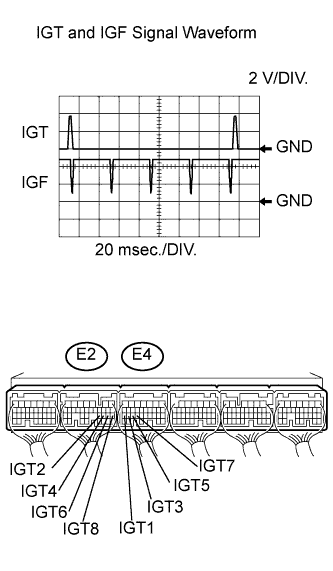 |
Inspect using an oscilloscope.
While cranking or idling, check the waveform of the ECM connectors.
| Tester Connection | Specified Condition |
| E4-32 (IGF1) - E3-1 (E1) E2-28 (IGF2) - E3-1 (E1) E4-27 (IGT1) - E3-1 (E1) E2-23 (IGT2) - E3-1 (E1) E4-26 (IGT3) - E3-1 (E1) E2-22 (IGT4) - E3-1 (E1) E4-25 (IGT5) - E3-1 (E1) E2-21 (IGT6) - E3-1 (E1) E4-24 (IGT7) - E3-1 (E1) E2-20 (IGT8) - E3-1 (E1) | Correct waveform is as shown |
|
| ||||
| OK | |
| 5.CHECK IF DTC OUTPUT RECURS |
Clear the DTC (see page Нажмите здесь).
Connect the intelligent tester to the DLC3.
Turn the engine switch on (IG) and turn the tester ON.
Enter the following menus: Powertrain / Engine / DTC.
Read DTCs.
| Display (DTC Output) | Proceed to |
| P0351, P0352, P0353, P0354, P0355, P0356, P0357 and/or P0358 are output | A |
| No output | B |
|
| ||||
| A | ||
| ||
