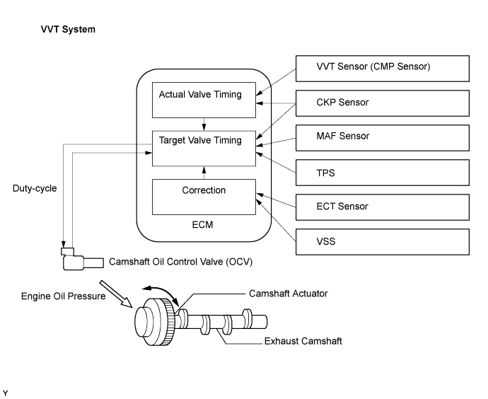
DTC    P0014    Camshaft Position "B" - Timing Over-Advanced or System Performance (Bank 1)

DTC    P0015    Camshaft Position "B" - Timing Over-Retarded (Bank 1)

DTC    P0024    Camshaft Position "B" - Timing Over-Advanced or System Performance (Bank 2)

DTC    P0025    Camshaft Position "B" - Timing Over-Retarded (Bank 2)

для подготовки Нажмите здесь


DESCRIPTION

УКАЗАНИЕ:
If DTC P0014, P0015, P0024 or P0025 is present, check the VVT (Variable Valve Timing) system.

The Variable Valve Timing (VVT) system includes the ECM, OCV and VVT controller. The ECM sends a target duty-cycle control signal to the OCV. This control signal regulates the oil pressure supplied to the VVT controller. Camshaft timing control is performed according to engine operating conditions such as the intake air volume, throttle valve position and engine coolant temperature. The ECM controls the OCV, based on the signals transmitted by several sensors. The VVT controller regulates the exhaust camshaft angle using oil pressure through the OCV. As a result, the relative positions of the camshaft and crankshaft are optimized, the engine torque and fuel economy improve, and the exhaust emissions decrease under overall driving conditions. The ECM detects the actual exhaust valve timing using signals from the VVT and crankshaft position sensors, and performs feedback control. This is how the target exhaust valve timing is verified by the ECM.

A130637E02


DTC No.
DTC Detection Condition
Trouble Area
P0014
P0024
Warm up the engine and engine idling.
Exhaust valve timing does not change for 1 minutes or more in advanced position
(2 trip detection logic):
  1. Valve timing
  2. Oil control valve (OCV) for exhaust side (bank 1, 2)
  3. Cylinder head cover sub-assembly (bank 1, 2)
  4. Camshaft timing exhaust gear assembly
  5. ECM
P0015
P0025
Warm up the engine and drive the vehicle.
Exhaust valve timing does not change for 5 minutes or more in retarded position
(1 trip detection logic):
  1. Valve timing
  2. OCV for exhaust side (bank 1, 2)
  3. Cylinder head cover sub-assembly (bank 1, 2)
  4. Camshaft timing exhaust gear assembly
  5. ECM

MONITOR DESCRIPTION

  1. The ECM optimizes the exhaust valve timing using the VVT (Variable Valve Timing) system to control the exhaust camshaft. The VVT system includes the ECM, the Oil Control Valve (OCV) and the VVT controller.
  2. The ECM sends a target duty-cycle control signal to the OCV. This control signal regulates the oil pressure supplied to the VVT controller. The VVT controller can advance or retard the exhaust camshaft.
    If the difference between the target and actual exhaust valve timing is large, and changes in actual exhaust valve timing are small, the ECM interprets this as the VVT controller stuck malfunction and sets a DTC.
    1. Example:
      A DTC is set when the following conditions A, B and C are met:
      1. The difference between the target and actual exhaust valve timing is more than 5°CA (Crankshaft Angle) and the condition continues for more than 4.5 seconds (Procedure "A").
      2. It takes 5 seconds or more to change the valve timing by 5°CA (Procedure "B").
      3. After above procedures "A" and "B" are met, the OCV is forcibly activated 63 times or more (Procedure "C").
  3. DTCs P0014 and P0024 (Advanced Cam Timing) are subject to 2 trip detection logic.
  4. DTCs P0015 and P0025 (Retarded Cam Timing) are subject to 1 trip detection logic.
    These DTCs indicate that the VVT controller cannot operate properly due to OCV malfunctions or the presence of foreign objects in the OCV.
  5. The monitor will not run unless the following conditions are met:
    1. The engine is warm (the engine coolant temperature is 75°C [167°F] or more).
    2. The vehicle has been driven at more than 40 mph (64 km/h) for 3 minutes.
    3. The engine has idled for 3 minutes (retarded angle side only).

WIRING DIAGRAM

Refer to DTC P0013 (see page Нажмите здесь).

INSPECTION PROCEDURE


УКАЗАНИЕ:

Abnormal bank
Advanced timing over
(Valve timing is out of specified range)
Retarded timing over
(Valve timing is out of specified range)
Bank 1
P0014
P0015
Bank 2
P0024
P0025
  1. If DTC P0014 or P0015 is displayed, check the bank 1 VVT system for exhaust side circuit.
  2. Bank 1 refers to the bank that includes cylinder No. 1.
  3. If DTC P0024 or P0025 is displayed, check the bank 2 VVT system for exhaust side circuit.
  4. Bank 2 refers to the bank that does not include cylinder No. 1.
  5. Read freeze frame data using the intelligent tester. Freeze frame data records the engine condition when malfunctions are detected. When troubleshooting, freeze frame data can help determine if the vehicle was moving or stationary, if the engine was warmed up or not, if the air-fuel ratio was lean or rich, and other data from the time the malfunction occurred.

1.CHECK ANY OTHER DTCS OUTPUT (IN ADDITION TO DTC P0014, P0015, P0024 OR P0025)
  1. Connect the intelligent tester to the DLC3.

  1. Turn the engine switch on (IG) and turn the tester ON.

  1. Enter the following menus: Powertrain / Engine / DTC.

  1. Read DTCs.

    Result:

    Display (DTC output)
    Proceed to
    P0014, P0015, P0024 or P0025
    A
    P0014, P0015, P0024 or P0025 and other DTCs
    B

    УКАЗАНИЕ:
    If any DTCs other than P0014, P0015, P0024 or P0025 are output, troubleshoot those DTCs first.


B
GO TO DTC CHART (Нажмите здесь)
A


2.PERFORM ACTIVE TEST BY INTELLIGENT TESTER (OPERATE OCV)
  1. Connect the intelligent tester to the DLC3.

  1. Start the engine and turn the tester ON.

  1. Warm up the engine.

  1. Enter the following menus: Powertrain / Engine / Active Test / VVT Exhaust Linear (Bank 1) or VVT Exhaust Linear (Bank 2).

  1. Check the engine speed while operating the Oil Control Valve (OCV) using the tester.

    OK:

    Tester Operation
    Specified Condition
    0%
    Normal engine speed
    30%
    Engine idles roughly


NG
Перейдите к шагу 4
OK


3.CHECK WHETHER DTC OUTPUT RECURS (DTC P0014, P0015, P0024 OR P0025)
  1. Connect the intelligent tester to the DLC3.

  1. Turn the engine switch on (IG) and turn the tester ON.

  1. Clear DTCs (see page Нажмите здесь).

  1. Start the engine and warm it up.

  1. Switch the ECM from normal mode to check mode using the tester (see page Нажмите здесь).

  1. Drive the vehicle for more than 10 minutes.

  1. Read DTCs using the tester.

    OK:
    No DTC output.


OK
END
NG


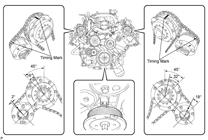
4.CHECK VALVE TIMING (CHECK FOR LOOSE AND JUMPED TEETH ON TIMING CHAIN)

A158482E01

  1. Remove the cylinder head cover RH and LH.

  1. Turn the crankshaft pulley, and align its groove with the timing mark "0" of the timing chain cover.

  1. Check that the timing marks of the camshaft timing gears aligned with the timing marks of the bearing cap as shown in the illustration.
    If not, turn the crankshaft 1 revolution (360°) and align the marks as above.

    OK:
    Timing marks on camshaft timing gears are aligned as shown in illustration.

  1. Reinstall the cylinder head cover.


NG
ADJUST VALVE TIMING (Нажмите здесь)
OK


5.INSPECT CAMSHAFT TIMING OIL CONTROL VALVE ASSEMBLY
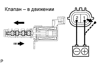

    A097066E01
  1. Remove the OCV.

  1. Measure the resistance according to the value(s) in the table below.

    Standard resistance:
    Tester Connection
    Condition
    Specified Condition
    1 - 2
    20°C (68°F)
    6.9 to 7.9 Ω

  1. Apply the positive battery voltage to terminal 1 and negative battery voltage to terminal 2. Check the valve operation.

    OK:
    Valve moves quickly.


NG
REPLACE CAMSHAFT TIMING OIL CONTROL VALVE ASSEMBLY (Нажмите здесь)
OK


6.INSPECT OIL CONTROL VALVE FILTER
  1. Remove the cylinder head cover sub-assembly (see page Нажмите здесь).

  1. Remove the OCV filter (see page Нажмите здесь).

  1. Inspect the OCV filter.

    OK:
    Filter is not clogged.


NG
REPLACE OIL CONTROL VALVE FILTER (Нажмите здесь)
OK


7.REPLACE CAMSHAFT TIMING EXHAUST GEAR ASSEMBLY
  1. Replace the camshaft timing exhaust gear (see page Нажмите здесь).


NEXT


8.CHECK WHETHER DTC OUTPUT RECURS
  1. Connect the intelligent tester to the DLC3.

  1. Turn the engine switch on (IG) and turn the tester ON.

  1. Clear DTCs.

  1. Start the engine and warm up.

  1. Switch the ECM from normal mode to check mode using the tester (see page Нажмите здесь).

  1. Warm up the engine.

  1. Idle it for 1 minutes.

  1. Drive the vehicle for more than 5 minutes.

  1. Read output DTCs using the intelligent tester.

    OK:
    No DTC output.

    УКАЗАНИЕ:
    DTC P0014, P0015, P0024 or P0025 is output when foreign objects in engine oil are caught in some parts of the system. These codes will stay registered even if the system returns to normal after a short time. These foreign objects are then captured by the oil, thus eliminating the source of the problem.


OK
SYSTEM OK
NG

REPLACE ECM (Нажмите здесь)