СИСТЕМА ПОСАДКИ И ЗАПУСКА > ОПИСАНИЕ СИСТЕМЫ |
| PUSH-BUTTON START DESCRIPTION |
The push-button start uses a push-type engine switch, which the driver can operate by merely carrying the key. This system consists primarily of the main body ECU, engine switch, ID code box, steering lock ECU, key, D-ACC relay, D-IG1 relay, IG2 relay and certification ECU. The main body ECU controls the system. This function operates in cooperation with the entry and start system. The table below shows the transition of the engine switch, which depends on whether the brake pedal is depressed or released.
This system has different power source mode patterns depending on the brake pedal and shift lever conditions.
| Condition | Power Source Mode Pattern |
| Brake pedal not depressed, shift lever in P | Each time engine switch is pushed
|
| Brake pedal not depressed | When engine switch is pushed in engine started condition
|
| Brake pedal depressed, shift lever in P or N | When engine switch is pushed once
|
| Brake pedal depressed, shift lever in P or N | When engine switch is pushed in on (ACC) condition
|
| Brake pedal depressed, shift lever in P or N | When engine switch is pushed in on (IG) condition
|
| Brake pedal depressed | When engine switch is pushed in engine started condition
|
| FUNCTION OF COMPONENT |
| Components | Function |
| Engine Switch (Transponder Key Amplifier) |
|
| Key |
|
| Indoor Key Oscillator |
|
| Door Control Receiver |
|
| Main Body ECU |
|
| Certification ECU |
|
| Park / Neutral Position Switch |
|
| Stop Light Switch |
|
| ID Code Box |
|
| ECM |
|
| SYSTEM FUNCTION |
| Control | Outline |
| Engine Switch Control |
|
| Diagnosis |
|
| CONSTRUCTION AND OPERATION |
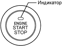 |
Engine switch:
The engine switch consists of a momentary type switch, 3 color (amber, green, greenish white) LEDs, and transponder key amplifier.
Indicator light condition:
| Power Source Mode/Condition | Indicator Light Condition | |
| Brake pedal released | Brake pedal depressed, shift lever in P or N, key certification passed | |
| Off | OFF | Illuminates (green) |
| On (ACC, IG) | Illuminates (amber) | Illuminates (green) |
| Engine running | OFF | OFF |
| Steering lock locked | Flashes (green) for 30 seconds | Flashes (green) for 30 seconds |
| System malfunction | Flashes (amber) for 15 seconds | Flashes (amber) for 15 seconds |
| Stop light switch with shift lever in P or N malfunction | Flashes (green) for 15 seconds | Flashes (green) for 15 seconds |
Main body ECU:
The main body ECU consists of the D-IG1 relay, D-ACC relay and IG2 relay actuation circuits and CPU.
| SYSTEM NOT OPERATING NORMALLY (DUE TO KEY BATTERY DEPLETION, ELECTRICAL NOISE, ETC.) |
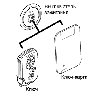 |
To operate the push-button start function when the key or card key battery is low or affected by wave noise, etc., touch the LEXUS mark of the key or card key to the engine switch while depressing the brake pedal with the shift lever in P or N.
The main body ECU transmits a key verification request signal from the stop light switch to the certification ECU.
The certification ECU does not receive an ID code response from the door control receiver, so it actuates the transponder key amplifier built into the engine switch.
The transponder key amplifier outputs an engine immobiliser radio wave to the key.
The key receives the radio wave, and returns a radio wave response to the transponder key amplifier.
The transponder key amplifier combines the key ID codes with the radio wave response, and transmits it to the certification ECU.
The certification ECU judges and verifies the ID code, and transmits a key verification OK signal to the main body ECU. The buzzer in the combination meter sounds at the same time.
After the buzzer sounds, with the shift lever in P or N, if the engine switch is pressed within 10 seconds with the brake pedal not depressed, the power source mode changes to on (ACC) or on (IG), as in the normal condition.
| DIAGNOSIS |
